Energy supply system for a water-bound device which has different connected zones

A technology for supplying energy and connecting parts, which is applied in the field of running the energy supplying system

Pending Publication Date: 2021-07-23
西门子能源全球有限两合公司 +1
View PDF12 Cites 0 Cited by
  • Summary
  • Abstract
  • Description
  • Claims
  • Application Information

AI Technical Summary

Problems solved by technology

Using an AC network with an AC energy bus for distributing electrical energy can be disadvantageous if the frequency is variable in high voltage levels

Method used


Image

  • Energy supply system for a water-bound device which has different connected zones
  • Energy supply system for a water-bound device which has different connected zones
  • Energy supply system for a water-bound device which has different connected zones

Examples


Embodiment Construction

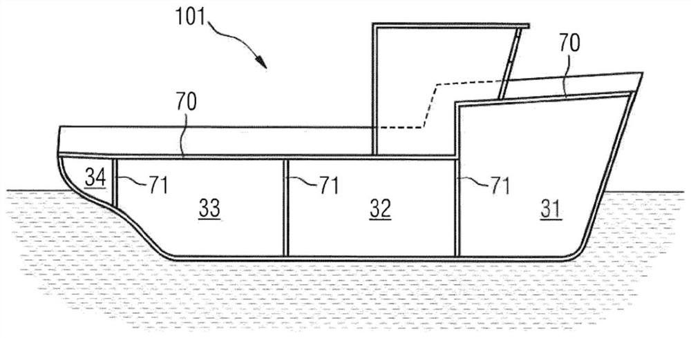
[0106] according to figure 1 The view of shows a ship 101 with a first subdivision into zones. A first zone 31 , a second zone 32 , a third zone 33 and a fourth zone 34 are shown, which are delimited by a bulkhead 71 . Another is achieved, for example, by a watertight deck 70 .

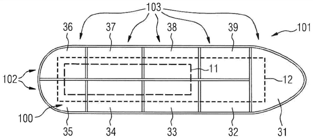
[0107] according to figure 2 The view in FIG. 1 shows a ship 101 with a second subdivision into zones 31 to 39 in plan and top view. The zones can also be divided into longitudinal zones 102 and transverse zones 103 . The energy supply system 100 extends over this area. The energy supply system has a first direct voltage bus 11 and a second direct voltage bus 12 . The DC voltage buses 11 and 12 run differently over the region. In another refinement, bulkheads in the longitudinal region can also be omitted. However, this is not shown.

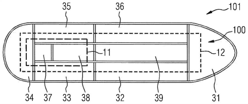
[0108] according to image 3 The view in FIG. 2 shows a ship 100 with a third subdivision into zones 31 to 39 , wherein zones 37 , 38 and 39 are central zones...


PUM


Abstract

The invention relates to an energy supply system (100) for a water-bound device (101) and in particular to a corresponding method. The system comprises a first DC voltage bus (11) for a first DC voltage; a second DC voltage bus (12) for a second DC voltage; and a first energy source (21) which has at least two supplying electrical connections (51, 52, 53) to the DC voltage buses (11, 12), wherein at least one of the DC voltage buses (11, 12) has sections (61, 62, 63, 64, 65, 66, 67).

Description

technical field [0001] The invention relates to an energy supply system for a water wading device, in particular a floating device. Floating installations are for example ships, submarines, oil platforms and / or gas platforms. Examples of ships are cruise ships, frigates, container ships, aircraft carriers, icebreakers, and the like. Floating devices are wading devices. An oil or gas platform built on the ocean floor is an example of a wading device. In addition to the energy supply system, the invention also relates to a corresponding method for operating the energy supply system. Background technique [0002] An energy supply system for a water wading device or a floating device has an energy source. If a floating device is mentioned below, this also means a wading device and vice versa. Examples of energy sources are diesel generators, fuel cells, batteries / batteries, flywheels, and the like. The diesel engine of the diesel generator can be operated, for example, wit...

Claims


Application Information

Patent Timeline
Patent Type & Authority Applications(China)
IPC IPC(8): H02J1/08H02J1/12H02J7/00H02J1/00
CPCH02J1/12H02J7/0034H02J2310/42H02J1/082B63H21/17B63H23/24B63J2003/002H02J1/002H02J1/084H02J1/10
Inventor 维科·舒尔茨沃尔夫冈·福斯
Owner 西门子能源全球有限两合公司
Why Eureka
Try Eureka