Pumping method in a system for pumping and system of vacuum pumps

a vacuum pump and pumping system technology, applied in the direction of machines/engines, liquid fuel engines, positive displacement liquid engines, etc., can solve the problems of system bulkiness, increase in the number of components of the system, complexity and cost, and achieve the effect of lowering the pressure there more quickly

Inactive Publication Date: 2017-02-16
ATELIERS BUSCH
View PDF8 Cites 2 Cited by
  • Summary
  • Abstract
  • Description
  • Claims
  • Application Information

AI Technical Summary

Benefits of technology

[0005]The present invention has as object to propose a pumping method in a pumping system making it possible to reduce the electrical energy necessary for putting a chamber under vacuum and for maintaining the vacuum in this chamber, as well as to achieve a decrease in the temperature of the exit gas.
[0011]According to a first aspect, the invention resides in the fact that the coupling of the primary lubricated rotary vane vacuum pump and of the ejector does not require measurements and specific devices (for example sensors for pressure, temperature, current, etc.), servo-controls or data management and calculation. Consequently, the pumping system suitable for implementing the pumping method according to the present invention comprises a minimal number of components, has great simplicity and is far less expensive than the existing systems.
[0021]When this non-return valve is open, the action of the ejector is felt very slightly as the pressure at its inlet is close to equal that at its outlet. In contrast, when the non-return valve closes at a certain pressure (because the pressure in the chamber has dropped in the meantime), the action of the ejector brings about a progressive reduction of the difference in pressure between the chamber and the conduit after the non-return valve. The pressure at the outlet of the primary lubricated rotary vane vacuum pump becomes that at the inlet of the ejector, that at its outlet being always the pressure in the conduit after the non-return valve. The more the ejector pumps, the more the pressure drops at the outlet of the primary lubricated rotary vane vacuum pump, in the closed space (limited by the non-return valve), and consequently the difference in pressure between the chamber and the outlet of the primary lubricated rotary vane vacuum pump decreases. This slight difference reduces the internal leaks in the primary lubricated rotary vane vacuum pump and causes at the same time a reduction of the pressure in the chamber, which makes it possible to improve the final vacuum. In addition, the primary lubricated rotary vane vacuum pump consumes less and less energy for the compression and produces less and less compression heat.
[0023]According to still another variant of the present invention, the flow of gas at the pressure necessary for the operation of the ejector is provided by a compressor. In a noteworthy way, this compressor can be driven by the primary lubricated rotary vane pump or, alternatively or in addition, in an autonomous way, independently of the primary lubricated rotary vane pump. This compressor can suction the atmospheric air or gases in the gas exit conduit after the non-return valve. The presence of such a compressor renders the lubricated rotary vane vacuum pump systems independent of a compressed gas source, which can meet the demands of certain industrial environments. The compressor can provide the flow of gas at the pressure necessary for the operation of a plurality of ejectors, respectively forming part of a plurality of vacuum pump systems having as primary pumps lubricated rotary vane pumps. The compressor forms part of the system also in the case of continuous operation of the ejector as well as in the case of its controlling according to the parameters, controlled by suitable sensors.
[0024]On the other hand, it is also evident that the study of the mechanical concept seeks to reduce the space between the gas outlet port of the primary lubricated rotary vane vacuum pump and the non-return valve with the aim of lowering the pressure there more quickly.

Problems solved by technology

This type of systems is bulky, operates either with by-pass valves presenting problems of reliability or by employing means of measurement, control, adjustment or servo-control.
However, these means of control, adjustment or servo-control must be controlled in an active way, which necessarily results in an increase in the number of components of the system, its complexity and its cost.

Method used


Image

  • Pumping method in a system for pumping and system of vacuum pumps
  • Pumping method in a system for pumping and system of vacuum pumps
  • Pumping method in a system for pumping and system of vacuum pumps

Examples


first embodiment

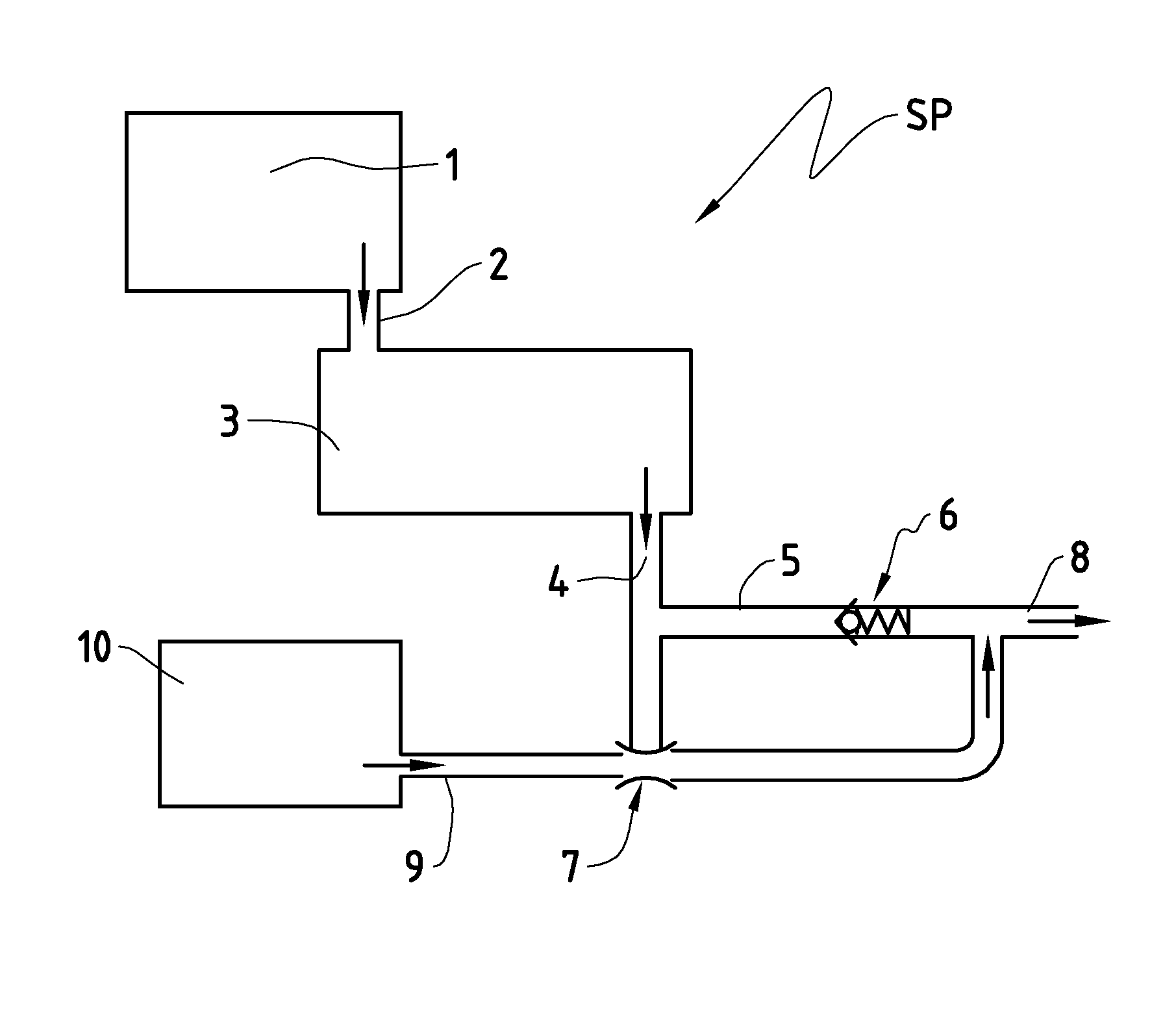
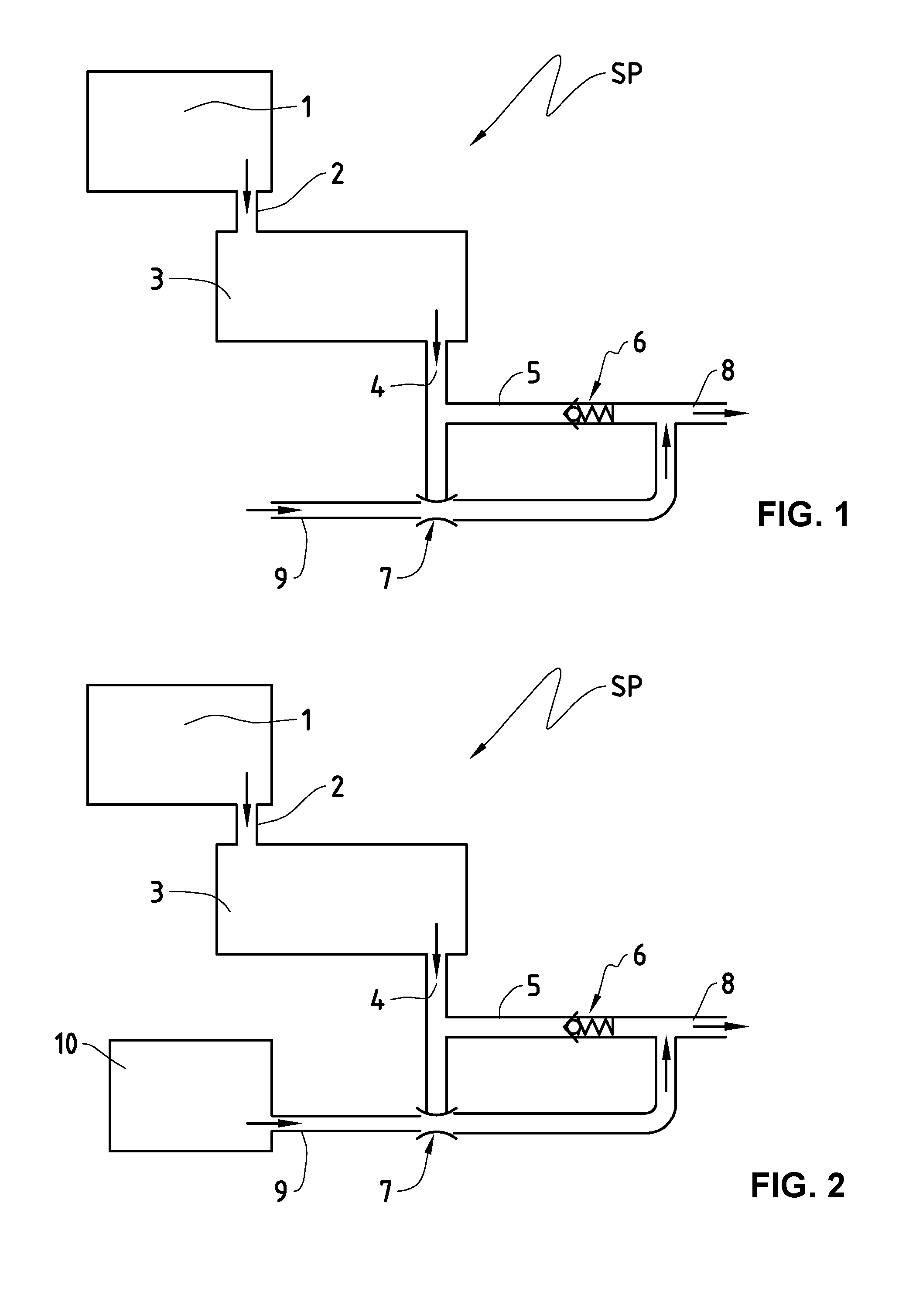
[0029]FIG. 1 represents a pumping system SP suitable for implementing a pumping method according to the present invention.

[0030]This pumping system SP comprises a chamber 1, which is connected to a suction port 2 of a primary lubricated rotary vane vacuum pump 3. The gas outlet port of the primary lubricated rotary vane vacuum pump 3 is connected to a conduit 5. A non-return discharge valve 6 is placed in the conduit 5, which after this non-return valve 6 continues into a gas exit conduit 8. The non-return valve 6, when it is closed, allows the formation of a space 4, contained between the gas outlet port of the primary vacuum pump 3 and itself. The pumping system SP also comprises an ejector 7, connected in parallel to the non-return valve 6. The suction port of the ejector is connected to the space 4 of the conduit 5, and its discharge port is connected to the conduit 8. The feed conduit 9 provides the working fluid for the ejector 7.

[0031]From the start of the primary lubricated ...


PUM


Abstract

The present invention relates to a pumping method in a pumping system (SP, SPP) comprising: a primary lubricated rotary vane vacuum pump (3) with a gas inlet port (2) connected to a vacuum chamber (1) and a gas outlet port (4) leading into a conduit (5) before coming out into the gas outlet (8) of the pumping system (SP, SPP), a non-return valve (6) positioned in the conduit (5) between the gas outlet port (4) and the gas outlet (8), and an ejector (7) connected in parallel to the non-return valve (6). According to this method, the primary lubricated rotary vane vacuum pump (3) is set into action in order to pump the gases contained in the vacuum chamber (1) through the gas outlet port (4). Simultaneously the ejector (7) is fed with working fluid, and the ejector (7) continues to be fed with working fluid all the while that the primary lubricated rotary vane vacuum pump (3) pumps the gases contained in the vacuum chamber (1) and / or all the while that the primary lubricated rotary vane vacuum pump (3) maintains a defined pressure in the vacuum chamber (1). The present invention also relates to a pumping system (SP, SPP) able to be used to implement this method.

Description

TECHNICAL FIELD OF THE INVENTION[0001]The present invention relates to a pumping method making it possible to reduce the consumption of electrical energy as well as improve the performance in terms of flow rate and final vacuum in a pumping system in which the main pump is a lubricated rotary vane vacuum pump. The invention likewise relates to a pumping system which can be used to achieve the method according to the present invention.PRIOR ART[0002]The general tendencies to increase the performance of vacuum pumps, to reduce the costs of installations and the consumption of energy in industries have brought significant developments in terms of performance, energy economy, bulkiness, in the drives, etc.[0003]The state of the art shows that to improve the final vacuum and to reduce the consumption of energy supplementary stages must be added in vacuum pumps of the multi-stage Roots or multi-stage claw type. For screw vacuum pumps there must be additional turns of the screw and / or the ...

Claims


Application Information

Patent Timeline
Patent Type & Authority Applications(United States)
IPC IPC(8): F04C23/00F04C18/344F04F5/20F04C29/02F04C29/00F04C25/02F04C28/06
CPCF04C23/005F04C25/02F04C18/344F04F5/20F04C29/02F04C29/0028F04C28/06F04B37/14F04F5/54
Inventor MULLER, DIDIERLARCHER, JEAN-ERICILTCHEV, THEODORE
Owner ATELIERS BUSCH
Why Eureka
Try Eureka