Drilling device for pile hole construction
A drilling device and a technology for pile holes, which are applied in the directions of driving devices, drilling equipment and methods, and drill bits for drilling in boreholes, can solve problems such as inability to continue drilling, damage to drill bits, and skewed pile holes, etc., and achieve improved drilling efficiency. Hole efficiency, increased bit life, avoiding skew and knocking shaft deformation effects
- Summary
- Abstract
- Description
- Claims
- Application Information
AI Technical Summary
Problems solved by technology
Method used
Image
Examples
Embodiment 1
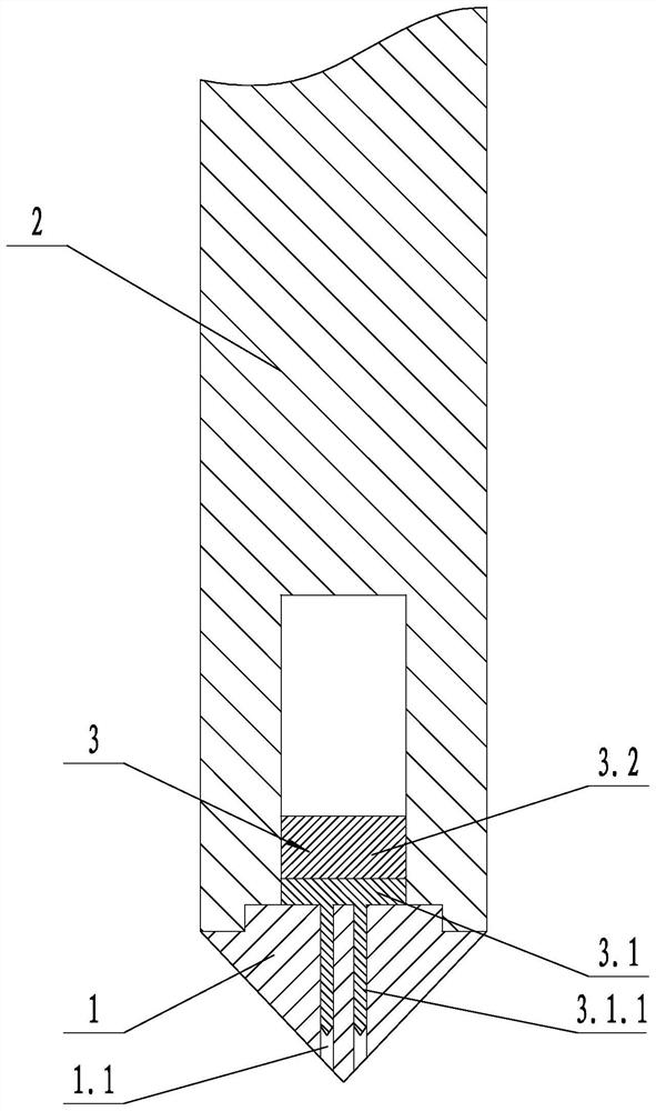
[0031] Such as figure 1 Shown, a kind of drilling device for pile hole construction, comprises drill bit 1, drill shaft 2 and striking device 3; Drill bit 1 is used for drilling underground, and drill bit 1 is provided with several passing holes 1.1; 2 is used to extend into the ground and transmit power to drive the drill bit 1 to rotate. The drill bit 1 is arranged on the lower end of the drill shaft 2, and a spiral guide plate is provided on the outer wall of the drill bit 1 and the drill shaft 2; To break the hard rocks in the ground, the striking device 3 is arranged in the drill shaft 2. The striking device 3 includes a striking drive mechanism 3.2 and a striking head 3.1. The striking head 3.1 is provided with several The point 3.1.1, the point 3.1.1 passes through the corresponding through-hole 1.1 and protrudes out of the drill bit 1 .
[0032] In the above technical solution, the axial dimension of the drill shaft 2 generally reaches tens of meters or even tens of m...
Embodiment 2
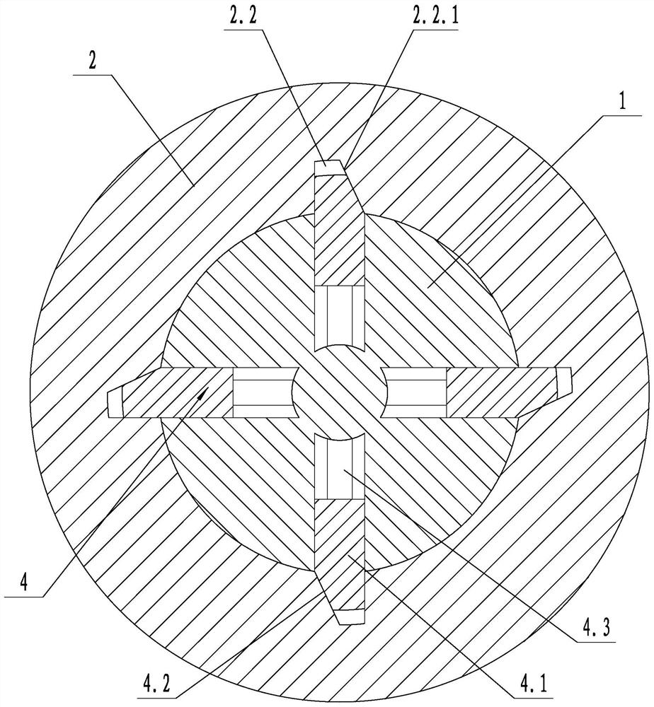
[0034] Such as figure 2 As shown, on the basis of Embodiment 1, a locking device 4 is also included, the drill bit 1 is rotationally connected with the drill shaft 2, and the rotating shaft of the drill bit 1 coincides with the rotating shaft of the drilling shaft 2; the side wall of the drilling shaft 2 is provided with a lock Tight groove 2.2, the side wall of the locking groove 2.2 is provided with a first slope 2.2.1, the locking device 4 includes a locking block 4.1 and a locking spring 4.3, the locking block 4.1 is slidingly connected with the drill bit 1, and the locking spring 4.3 One end is connected to the locking block 4.1, the other end of the locking spring 4.3 is connected to the drill bit 1, one end of the drill bit 1 extends into the locking groove 2.2, and the end of the drill bit 1 extending into the locking groove 2.2 is provided with the first inclined surface 2.2. 1 Adaptive and contacting second bevel 4.2. The structure can realize the rotary connection...
Embodiment 3
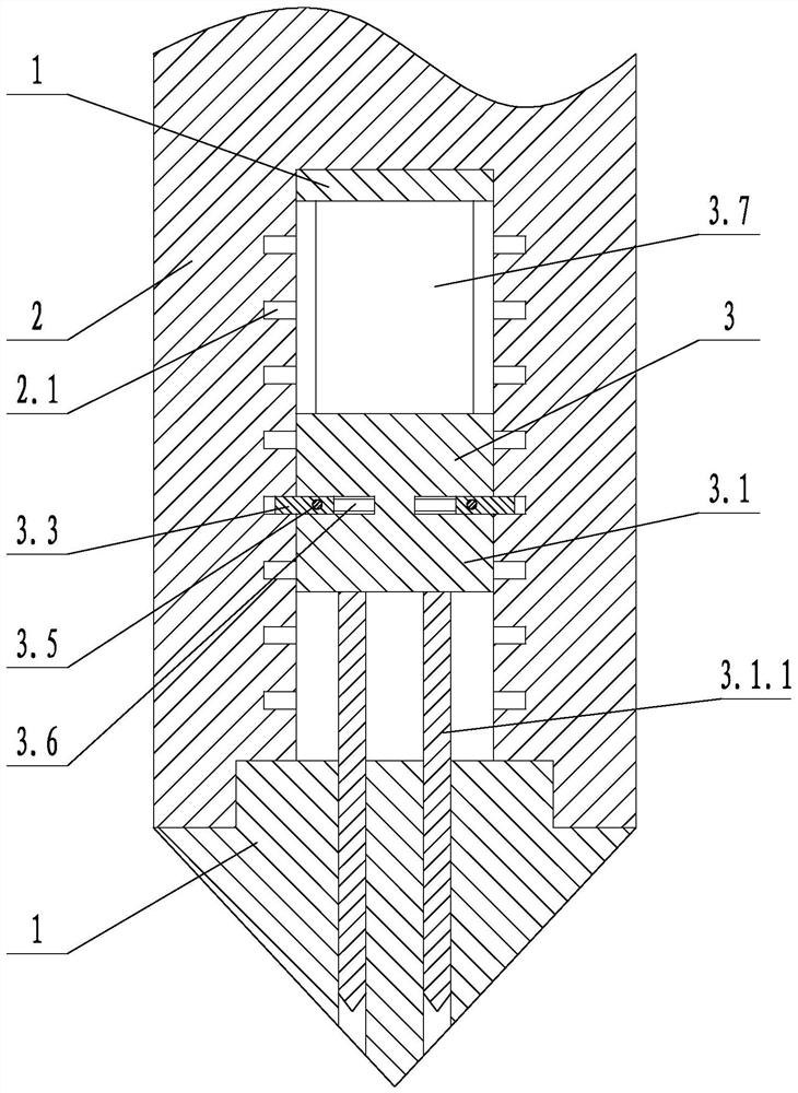
[0036] Such as figure 2 and Figure 4 As shown, on the basis of Embodiment 2, the striking head 3.1 is slidably connected with the drill bit 1 in the vertical direction, and the striking driving mechanism 3.2 includes a lifting block 3.3, a guide block 3.4, a contact block 3.5, a first telescopic spring 3.6 and The second telescopic spring 3.7, the inner side wall of the drill shaft 2 is provided with a spiral groove 2.1, one end of the lifting block 3.3 is connected with the striking head 3.1 along the horizontal sliding, the other end of the lifting block 3.3 extends into the spiral groove 2.1, the first telescopic spring 3.6 One end of the first telescopic spring 3.6 is connected with the lifting block 3.3, the other end of the first telescopic spring 3.6 is connected with the striking head 3.1, the guide block 3.4 is fixed with the drill bit 1, the guide block 3.4 is provided with a guide ring groove 3.4.1, and the guide ring groove 3.4.1 is set In the vertical plane, on...
PUM
 Abstract
Description
Claims
Application Information
 - R&D Engineer
- R&D Manager
- IP Professional
- Industry Leading Data Capabilities
- Powerful AI technology
- Patent DNA Extraction
Browse by: Latest US Patents, China's latest patents, Technical Efficacy Thesaurus, Application Domain, Technology Topic, Popular Technical Reports.
© 2024 PatSnap. All rights reserved.Legal|Privacy policy|Modern Slavery Act Transparency Statement|Sitemap|About US| Contact US: help@patsnap.com


