
A rectification structure of a multi-blade centrifugal fan for a compressor cooling system

A centrifugal fan and cooling system technology, which is applied in the field of compressors, can solve the problems affecting the use of heat exchangers, excessive local flow velocity, and uneven distribution, so as to improve market competitiveness, meet heat exchange needs, and evenly distribute airflow

Active Publication Date: 2022-07-19
HEFEI GENERAL MACHINERY RES INST +1
View PDF8 Cites 0 Cited by
  • Summary
  • Abstract
  • Description
  • Claims
  • Application Information

AI Technical Summary

Problems solved by technology

But in fact, affected by the secondary flow, the airflow at the outlet of the diffuser is as follows: Figure 8 The severe uneven distribution shown, when the air flow distribution at the outlet of the diffuser is uneven, the local flow velocity is either too large or too small, which will have an important impact on the heat transfer efficiency of the heat exchanger outlet. When the cooling air volume of the oil cooler is insufficient It will reduce the life of the lubricating oil, and oxidation, carbonization or decomposition will occur. When the cooling air volume of the oil cooler is excessive, the exhaust gas temperature will be lower than the dew point temperature, and water will be precipitated in the oil-gas mixture, which will cause the lubricating oil to emulsify; When the cooling of the intercooler is insufficient, higher requirements will be placed on the drying capacity of the rear end. When the cooling of the intercooler is excessive, the heat exchanger is prone to ice blockage when the unit is running at low temperature, which seriously affects the use of the heat exchanger.
[0004] Due to the existence of the secondary flow, the air volume provided by the multi-blade centrifugal fan may not be able to meet the heat exchange requirements of the heat exchanger. If the air volume of the fan is greatly increased, the aerodynamic noise of the fan will inevitably increase; the existing multi-blade centrifugal fan The improvement of the volute can reduce the secondary flow in the volute, but it cannot completely eliminate the secondary flow, so it needs to be solved urgently

Method used


Image

  • A rectification structure of a multi-blade centrifugal fan for a compressor cooling system
  • A rectification structure of a multi-blade centrifugal fan for a compressor cooling system
  • A rectification structure of a multi-blade centrifugal fan for a compressor cooling system

Examples


Embodiment Construction

[0033] The technical solutions in the embodiments of the present invention will be clearly and completely described below with reference to the accompanying drawings in the embodiments of the present invention. Obviously, the described embodiments are only a part of the embodiments of the present invention, rather than all the embodiments. Based on the embodiments of the present invention, all other embodiments obtained by those of ordinary skill in the art without creative efforts shall fall within the protection scope of the present invention.

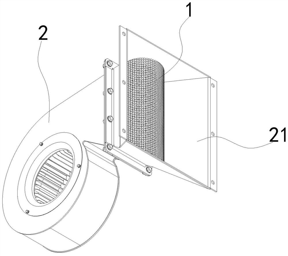
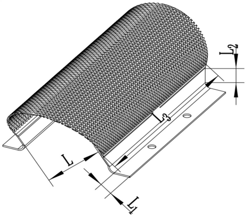
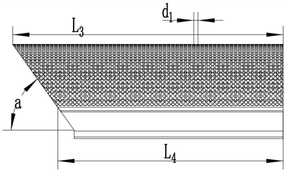
[0034] see Figures 1 to 9 In the embodiment of the present invention, a rectification structure of a multi-blade centrifugal fan for a compressor cooling system includes a rectification net 1 fixed in the multi-blade centrifugal fan 2, and the multi-blade centrifugal fan 2 includes a current collector, an impeller, a volute and diffuser 21. The diffuser 21 is connected to a heat exchanger, and the heat exchanger here includes a gas...


PUM


Abstract

The invention discloses a rectification structure of a multi-blade centrifugal fan used in a compressor cooling system. It is arranged between the outlet of the volute of the multi-blade centrifugal fan and the outlet of the diffuser, and the rectifying net is provided with guide holes, and the total area of ​​the holes of the guide holes is larger than the inlet area of ​​the diffuser. The invention basically eliminates the secondary flow generated in the volute by adding a rectifying net with a total hole area greater than the diffuser inlet area between the volute outlet of the multi-blade centrifugal fan and the diffuser outlet, and achieves vortex breaking. After the airflow passes through the rectifier net, the local flow rate is too large or too small to be improved, the overall airflow distribution is uniform, and the heat exchange efficiency of the heat exchanger connected to the diffuser is greatly improved. The heat exchange requirements of the heat exchanger are met.

Description

technical field [0001] The invention relates to the field of compressors, in particular to a rectification structure of a multi-blade centrifugal fan used in a compressor cooling system. Background technique [0002] The forward multi-blade centrifugal fan is widely used in the cooling system of air compressors because of its advantages of large flow coefficient, high pressure coefficient and low noise. With the continuous improvement of the multi-blade centrifugal fan, its shortcomings have gradually been exposed. When the forward multi-blade centrifugal fan is working, the gas undergoes two processes of radial-axial and axial-radial transformation during the process of entering the impeller from the collector. The distribution along the axial direction is extremely uneven, and the airflow load is mainly inclined to the vicinity of the rear disk, resulting in the airflow mainly concentrated in the middle and rear of the impeller, while the part of the impeller close to the...

Claims


Application Information

Patent Timeline
Patent Type & Authority Patents(China)
IPC IPC(8): F04D29/44F04D29/66F04D29/02F04D17/16F04D25/08
CPCF04D29/441F04D29/667F04D29/023F04D17/16F04D25/08
Inventor 刘志龙刘晓明谢传东舒悦曹斌朱全琛
Owner HEFEI GENERAL MACHINERY RES INST
Learn More