Full-floating piston pin friction test device
A test device and piston pin technology, which is applied in the field of power machinery, can solve problems such as the inability to apply piston pin friction and wear tests, and achieve the effects of improving test accuracy, consistency, and accuracy
- Summary
- Abstract
- Description
- Claims
- Application Information
AI Technical Summary
Problems solved by technology
Method used
Image
Examples
Embodiment 1
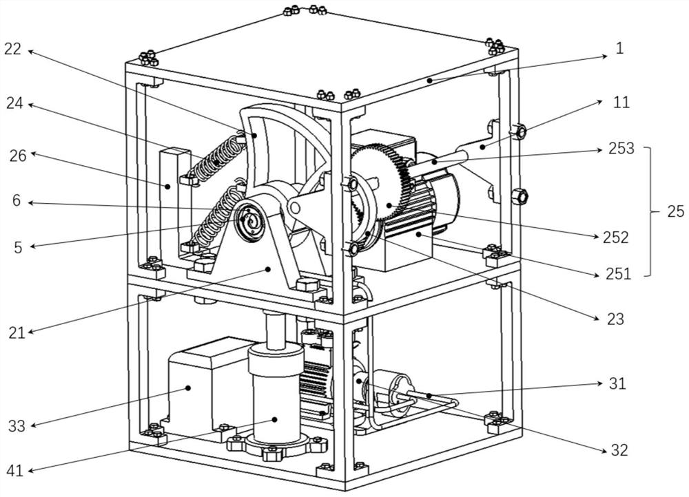
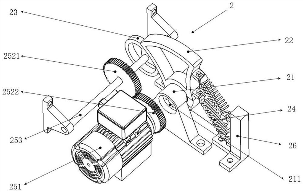
[0036] The invention provides a full-floating piston pin friction test device, such as Figure 1-9 As shown, it includes a frame 1 and a motion simulation system 2 installed on the frame 1 . The frame 1 is a frame structure, preferably a rectangular double-layer frame structure, which can provide installation positions for multiple supporting equipment, and saves the floor space of the frame. The upper, middle and lower positions of the frame 1 are supporting steel plates. The metal brackets are used for support, and the brackets are connected with the plates through high-strength bolts. The motion simulation system 2 includes a bearing base 21 , a connecting rod 22 , a cam 23 , a return spring 24 and a transmission mechanism 25 . The bearing seat 21 is provided with a shaft hole 211, and the shaft hole 211 is used for installing the piston pin 6 to be tested. The bearing seat 21 can be rectangular, triangular, Ω-shaped, etc. Two load-bearing bases 21 are fixedly installed ...
Embodiment 2
[0041] This embodiment 2 is formed on the basis of embodiment 1. Through the matching settings of lubrication, heating, loading and other systems, the consistency between the test process of the full-floating piston pin friction experiment and the actual working conditions is further improved, and the accuracy of the test is improved. . specifically:
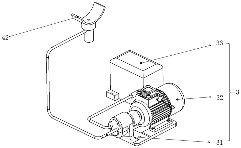
[0042] Such as Figure 1-9 As shown, a lubrication system 3 is provided in the full-floating piston pin friction test device, and the lubrication system includes an oil injection pipe 31 , an oil pump 32 and an oil tank 33 . The oil pump 32 and the oil tank 33 are installed and fixed on the bottom plate of the lower frame of the frame 1. The oil pump 32 is connected with the oil tank 33 through pipelines, and the oil injection pipe 31 is communicated with the output pipe of the oil pump 32. The oil injection pipe 31 is a single multi-joint or multiple , the oil injection pipe 31 is connected with the small end of the connectin...
Embodiment 3
[0054] Embodiment 3 is formed on the basis of Embodiment 2, and realizes the collection and control of the operation data of each system through the matching control system to improve the test accuracy. specifically:
[0055] Such as Figure 1-9 As shown, the full-floating piston pin friction test device is also equipped with a control system. The control system mainly includes a central controller, which is electrically connected to the motion simulation system 2, the lubrication system 3, the loading system 4 and the heating system 5. The controller adjusts the operating parameters of each system through the feedback mechanism by receiving the corresponding operating data of the motion simulation system 2, the lubrication system 3, the loading system 4, and the heating system 5, including receiving the data transmitted by the angle sensor, the flow sensor, and the temperature sensor in real time. . The central controller receives the real-time detection data fed back by th...
PUM
 Abstract
Description
Claims
Application Information
 - R&D Engineer
- R&D Manager
- IP Professional
- Industry Leading Data Capabilities
- Powerful AI technology
- Patent DNA Extraction
Browse by: Latest US Patents, China's latest patents, Technical Efficacy Thesaurus, Application Domain, Technology Topic, Popular Technical Reports.
© 2024 PatSnap. All rights reserved.Legal|Privacy policy|Modern Slavery Act Transparency Statement|Sitemap|About US| Contact US: help@patsnap.com


