
Synchronous motor control system and control method

A synchronous motor and control method technology, applied in control systems, AC motor control, motor vibration suppression control, etc., can solve the problems of easy failure of drive modules, damage to power devices, switching of power devices, etc., to optimize overall performance, reduce cost, the effect of reducing jitter

Active Publication Date: 2021-07-27
国华(青岛)智能装备有限公司
View PDF10 Cites 0 Cited by
  • Summary
  • Abstract
  • Description
  • Claims
  • Application Information

AI Technical Summary

Problems solved by technology

For example, in the current electric car control, the frequency usually used is 10K. When the car is running at high speed, the switching times of the motor are the same as the switching speed at low speed. This will easily cause the power device to switch frequently, resulting in damage to the device.
[0005] Therefore, in view of this situation, it is urgent to design and produce a synchronous motor control system and control method to solve the problem that the drive module is prone to failure, the motor is prone to vibration, and the power device is damaged in the prior art.

Method used


Image

  • Synchronous motor control system and control method
  • Synchronous motor control system and control method
  • Synchronous motor control system and control method

Examples


Embodiment Construction

[0046] In order to make the object, technical solution and advantages of the present invention clearer, the present invention will be further described in detail below in conjunction with the accompanying drawings and specific embodiments. It should be understood that the specific embodiments described here are only used to explain the present invention, not to limit the present invention.

[0047] Device embodiment

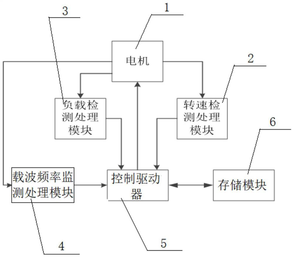
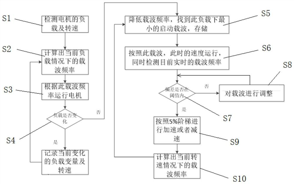
[0048] like figure 1 As shown, a synchronous motor control system provided in this embodiment includes a load detection processing module 3 , a rotational speed detection processing module 2 , a carrier frequency monitoring processing module 4 , a control driver 5 , and a storage module 6 . The input ends of the load detection processing module 3, the rotational speed detection processing module 2, and the carrier frequency monitoring processing module 4 are respectively connected to the motor 1, and the output ends of the load detection processing module 3, the...


PUM


Abstract

The invention belongs to the technical field of motor control, and particularly relates to a synchronous motor control system and method, and the system comprises a load detection processing module, a rotating speed detection processing module, a carrier frequency monitoring processing module, a control driver, and a storage module. The input ends of the load detection processing module, the rotating speed detection processing module and the carrier frequency monitoring processing module are respectively connected with the motor, the output ends of the load detection processing module, the rotating speed detection processing module and the carrier frequency monitoring processing module are respectively connected with the input end of the control driver, and the output end of the control driver is connected with the motor. The system can accurately control the motor by adopting different carrier frequencies and parameters according to the running state of the motor at different stages, different rotating speeds and different loads, so that the jitter of the motor can be reduced, the risk of damage of a power device can be reduced, and the service life of the motor can be prolonged.

Description

technical field [0001] The invention belongs to the technical field of motor control, and in particular relates to a synchronous motor control system and a control method. Background technique [0002] With the development of power electronics technology and the rapid development of electrical equipment technology, the motor has become an executive mechanism that must be involved in various electrical equipment, and energy saving and efficiency enhancement have also become the development trend of the electrical equipment industry. [0003] Motors are divided into asynchronous motors and synchronous motors. Due to the rapid development of semiconductor technology, frequency conversion speed regulation technology has been continuously improved and improved. The frequency converters that have been gradually improved are widely used in asynchronous motors for their good output waveforms and excellent performance-price ratio. application. [0004] However, for the control of sy...

Claims


Application Information

Patent Timeline
Patent Type & Authority Applications(China)
IPC IPC(8): H02P6/00H02P6/08H02P6/34H02P23/00H02P23/04H02P23/14
CPCH02P6/005H02P6/08H02P6/34H02P23/0077H02P23/04H02P23/14
Inventor 王广胡秋实杨雪娇贾永茂范作轩刘锦玉
Owner 国华(青岛)智能装备有限公司
Learn More