
Welding drilling device applied to formwork

A technology of punching device and template, applied in positioning device, clamping, supporting and other directions, can solve the problems of inconsistent size, prone to error, slurry leakage, etc., and achieve the effect of ensuring stability

Active Publication Date: 2021-07-30
CHINA METALLURGICAL CONSTR ENG GRP
View PDF10 Cites 0 Cited by
  • Summary
  • Abstract
  • Description
  • Claims
  • Application Information

AI Technical Summary

Problems solved by technology

[0004] The above scheme can only be applied before the formwork is set up. Therefore, when the formwork is set up, it is easy to appear that the size of the hole opened at the fixed position is inconsistent with the size of the embedded casing, and there is a risk of grout leakage; secondly, it is installed on site. At the same time, due to the large number of formwork, it is easy to appear that some formwork has not been opened before the formwork is supported, and it is necessary to replace the formwork or re-open the hole on site, thus prolonging the construction progress; finally, because the position of the formwork hole is usually It is measured manually, so it is prone to error

Method used


Image

  • Welding drilling device applied to formwork

Examples


Embodiment Construction

[0028] The present invention will be described below in conjunction with the accompanying drawings and embodiments.

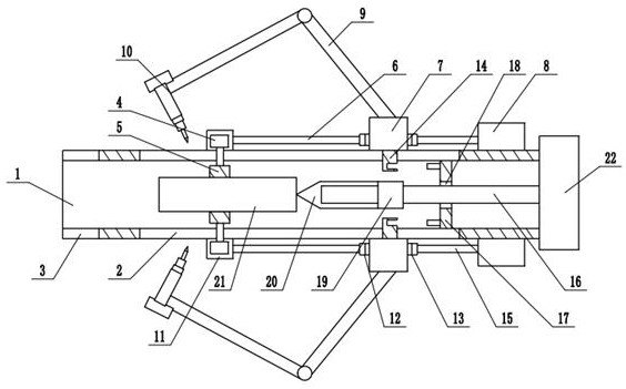
[0029] This example: see figure 1 , the welding and punching device applied to the formwork, including the positioning cylinder 1 facing the template and the embedded sleeve 21 located in the positioning cylinder 1, the positioning cylinder 1 is provided with three slides distributed in the circumferential direction with the center line as the center of the circle along the length direction of the positioning cylinder 1. Groove 2, each chute 2 is provided with a clamping piece that slides along its length and can be used to clamp the embedded sleeve 21; the outside of the positioning cylinder 1 is provided with a rotating ring 7, and the corresponding setting is directly below the rotating ring 7 In the ring groove on the positioning cylinder 1, one side of the rotating ring 7 is connected to the clamping member through the first push rod 6, and a left magnet a...


PUM


Abstract

The invention discloses a welding drilling device applied to a formwork. The welding drilling device applied to the formwork comprises a locating cylinder facing the formwork and an embedded sleeve located in the locating cylinder, wherein three sliding grooves distributed in the circumferential direction with the center line as the circle center are formed in the locating cylinder in the length direction of the locating cylinder; each sliding groove is provided with a clamping piece which slides in the length direction of the sliding groove and can be used for clamping the embedded sleeve; a rotating ring is arranged outside the locating cylinder in a sleeving mode; and a drilling mechanism is arranged in the locating cylinder. The welding drilling device applied to the formwork further comprises a microprocessor, wherein the microprocessor is connected with a transverse air cylinder, a tin soldering mechanism and a driving motor separately; and then the microprocessor issues an instruction to the driving motor, controls an output shaft of the driving motor to rotate anticlockwise, and drives a lead screw to rotate anticlockwise, and under the action of a second one-way bearing, the lead screw drives a drill bit to move in the length direction of the lead screw and penetrate through the embedded sleeve to carry out drilling and holing on the formwork.

Description

technical field [0001] The invention relates to the technical field of building construction, in particular to a welding and punching device applied to a formwork. Background technique [0002] When the formwork is set up, some places often need to reserve sleeves. At this time, it is necessary for the carpenter to make holes in the fixed position of the formwork before the formwork is set up. The holes made by ordinary methods are irregular and the work efficiency is low. , if there is a large gap between the embedded casing and the concrete, it is easy to leak the grout when pouring the concrete, resulting in defects in the quality of the concrete. [0003] In order to solve the above technical problems, the Chinese patent document (publication number is CN209792675U) discloses a simple template hole opening device, which includes a main body of an electric drill and a drill bit. There are positive 7-shaped outriggers and inverted 7-shaped outriggers arranged oppositely. ...

Claims


Application Information

Patent Timeline
IPC IPC(8): B23P23/02B23Q3/00
CPCB23P23/02B23Q3/00
Inventor 姚龙刘康邓子望
Owner CHINA METALLURGICAL CONSTR ENG GRP
Learn More