Aluminum alloy profile machining system
A technology of aluminum alloy profile and processing system, which is applied in the direction of metal processing equipment, manufacturing tools, grinding workpiece supports, etc., and can solve problems affecting installation and appearance
- Summary
- Abstract
- Description
- Claims
- Application Information
AI Technical Summary
Problems solved by technology
Method used
Image
Examples
Embodiment 1
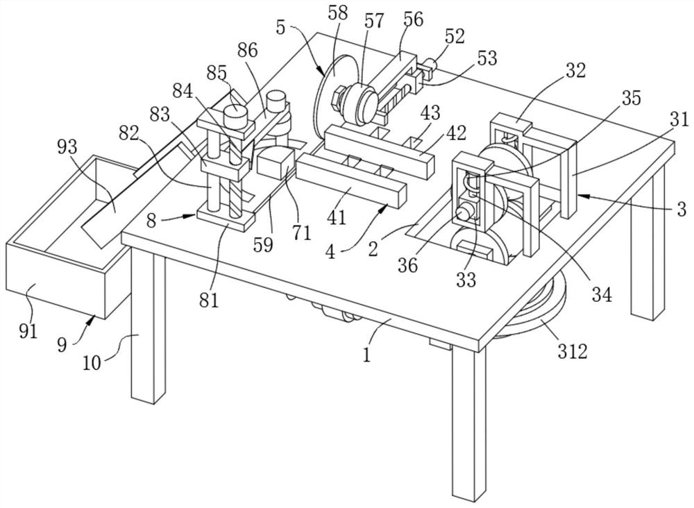
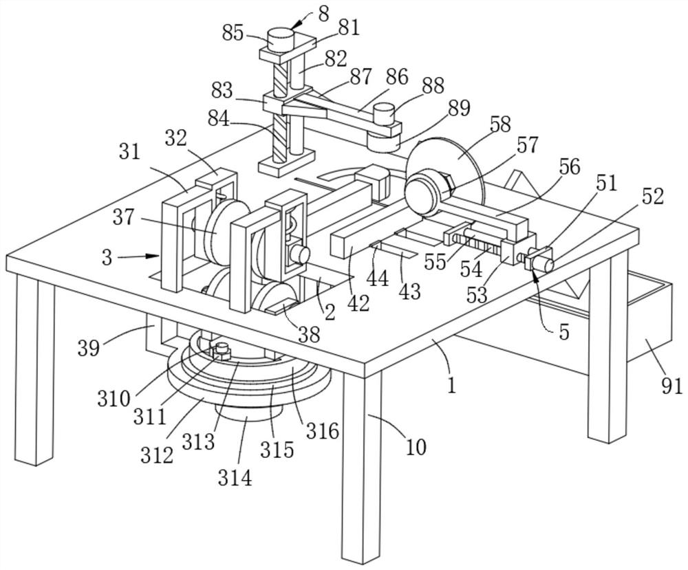
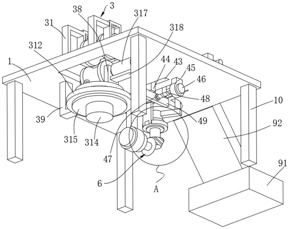
[0052] Example 1: Please refer to Figure 1-6 and Figure 8 , an aluminum alloy profile processing system, comprising:
[0053] The platform 1 has a through groove 2 on one side of the top; it also includes legs 10 , and the bottom of the platform 1 is supported by four legs 10 .
[0054] Profile feed unit 3, which includes a feed assembly, a speed control assembly and a buffer assembly, and is installed at the slot 2 on the platen 1;
[0055] The feed assembly includes a bent rod 31, a square mounting frame 32, a movable mounting block 33, an end shaft 36, a feed roller 37, a mounting plate 38, a rotating disc 316, a feed motor 317 and a feed motor seat 318, and the table plate 1 A rotating disk 316 is provided at the position corresponding to the through groove 2 below, and two corresponding mounting plates 38 are arranged on the rotating disk 316, a feed roller 37 is arranged between the two mounting plates 38, and the two ends of the feed roller 37 pass through The end ...
Embodiment 2
[0075] Example 2: Please refer to Figure 7 , an aluminum alloy profile processing system, the structure of this embodiment is roughly the same as that of Embodiment 1, the difference is that:
[0076] The bending angle blocking unit 7 includes a blocking block 71, a clamping column 72, an inner blind groove 76, a clamping spring 77 and a clamping ball 78, and a blind hole is opened on the platen 1 at the center of the semicircular arc groove 610, A clamp post 72 is interspersed in the blind hole, and the top of the clamp post 72 is provided with a blocking block 71, the blocking block 71 is a square block and one of the corners is rounded, and both sides of the blind hole are symmetrically provided with an inner blind groove 76, A snapping ball 78 is connected to the blind slot 76 via a snapping spring 77 , and the snapping ball 78 snaps into the hemispherical snapping grooves on both sides of the snap post 72 under the elastic force of the snapping spring 77 .
[0077] The ...
Embodiment 3
[0078] Example 3: Please refer to figure 2 , an aluminum alloy profile processing system, the structure of this embodiment is roughly the same as that of the above embodiment, the difference is that:
[0079] The bending grinding unit 8 also includes a grinding motor 88, and the extension rod 86 is fixed with a grinding motor 88 on the top of one end away from the movable block 2 83, and the bottom output shaft of the grinding motor 88 passes through the end of the extension rod 86 and is connected to Grind the bottom center of disc 89. The work of the grinding motor 88 can drive the grinding disc 89 to rotate, and can grind the wrinkles at the bend. This method has the risk of damaging the structural strength of the aluminum alloy bend, so it needs to be used with caution.
PUM
 Abstract
Description
Claims
Application Information
 - R&D
- Intellectual Property
- Life Sciences
- Materials
- Tech Scout
- Unparalleled Data Quality
- Higher Quality Content
- 60% Fewer Hallucinations
Browse by: Latest US Patents, China's latest patents, Technical Efficacy Thesaurus, Application Domain, Technology Topic, Popular Technical Reports.
© 2025 PatSnap. All rights reserved.Legal|Privacy policy|Modern Slavery Act Transparency Statement|Sitemap|About US| Contact US: help@patsnap.com


