Anti-collision device

A technology of anti-collision devices and damping devices, which is applied in construction, bridge construction, bridges, etc., can solve problems such as premature failure, damage to energy-consuming devices, and limited energy-consuming components, and achieve a large range of protection capabilities and energy-consuming processes. Smooth, energy-efficient way of environmental protection

Active Publication Date: 2021-07-30
HUNAN UNIV
View PDF5 Cites 0 Cited by
  • Summary
  • Abstract
  • Description
  • Claims
  • Application Information

AI Technical Summary

Problems solved by technology

[0003] This type of steel fender was widely used as anti-collision devices in bridges, but a series of problems were exposed during use: (1) The outer panel of the steel fender is generally thin, and it is easy to be prematurely damaged during the collision , so that the internal energy-dissipating components participating in the deformation are very limited, and the energy-dissipating efficiency is low
(2) Because the internal energy-dissipating components are mainly isotropic lattice steel plates with similar horizontal and vertical stiffness, the failure mode of the structure under collision is difficult to control, and the energy-dissipating capacity of the structure cannot be accurately estimated and designed; (3 ) The steel structure is easy to corrode when it is at the junction of the water surface, and its durability is poor, and it may even be a vulnerable component in the design of the whole life cycle of the bridge; For flammable and explosive goods, a collision may cause serious fire, explosion and other accidents
[0004] Although measures such as adding horizontal stiffeners to the steel fender can increase the rigidity of the outer panel to a certain extent, other defects of the steel fender cannot be solved
At present, the relatively new type of anti-collision device is the FRP flexible anti-collision buoy box. Due to the material characteristics of FRP itself, this type of anti-collision facility has inherent short board defects, such as: (1) FRP material anisotropy, vertical fiber direction The strength and elastic modulus are too low; (2) The interlayer tensile strength and interlayer shear strength of FRP are very low, and it is difficult to connect multi-layer FRP (3) The elastic modulus of FRP material is small, about 1 / 20- 1 / 2, it is necessary to rely on the geometric stiffness of the component to make up for the lack of stiffness; (4) The fire resistance of FRP materials is poor, and the critical temperature is only about 300 ° C, although it can be improved by adding flame retardants, which makes the price itself high FRP is even less economical; (5) The production process of FRP flexible anti-collision floating tank is relatively complicated, because it is difficult to guarantee product quality because it is formed by hand lay-up process
In addition, when a ship collides with the anti-collision device, most of the energy-consuming devices will be damaged to a considerable extent due to the way of energy consumption. After the accident, the protective device needs to be repaired or replaced in time
[0005] This kind of protective device that uses energy consumption methods such as plastic deformation and fracture energy consumption often needs to be maintained and replaced many times during use, especially in areas such as bridges and docks in the flight section where collision accidents occur frequently. Anti-collision devices maintenance costs are higher
Considering the whole life cycle of the device, traditional energy-consuming forms of anti-collision facilities are difficult to reduce the cost of protection

Method used


Image

  • Anti-collision device
  • Anti-collision device
  • Anti-collision device

Examples


Embodiment 1

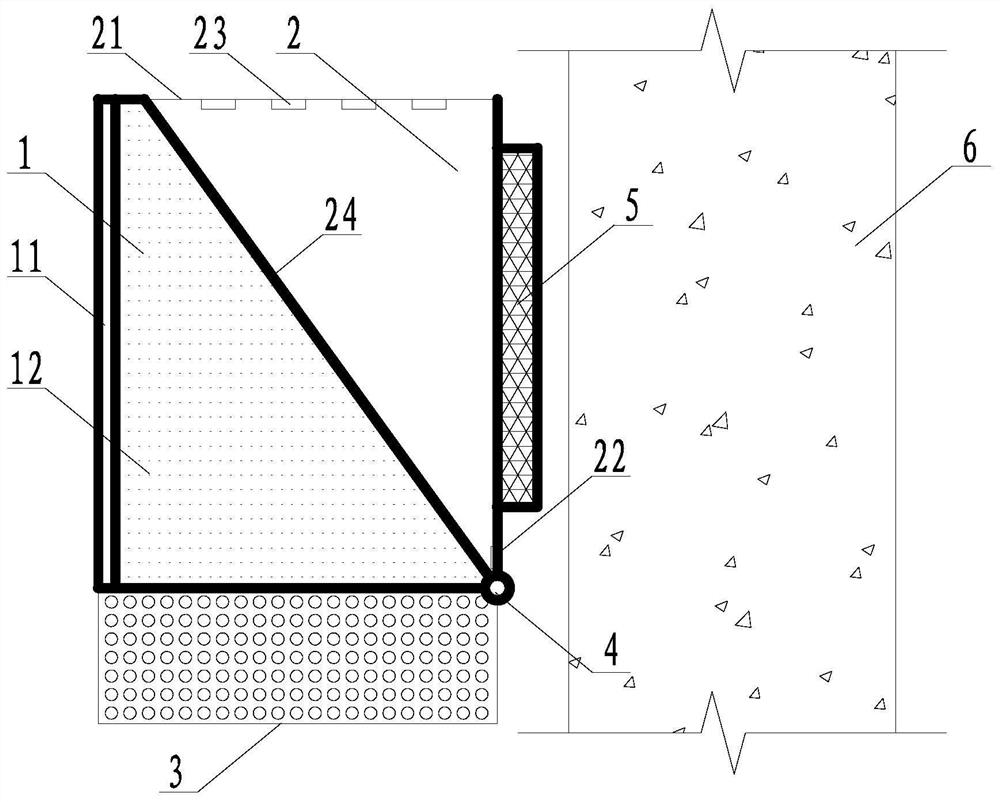
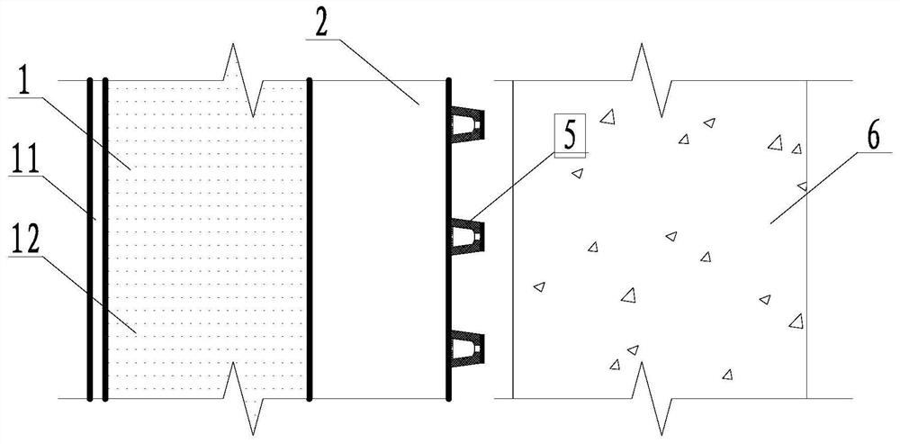
[0049] Such as figure 1 , figure 2 As shown, the anti-collision device of this embodiment is used for the anti-collision of the bridge pier 6, including a force transmission assembly 1 and a water tank 2 containing a water medium inside; the force transmission assembly 1 includes a collision panel 11 and is connected to the collision panel The energy-dissipating material layer 12 on one side of 11, the collision panel 11 is set on the side of the force transmission component 1 that is subjected to impact, and is composed of ultra-high performance concrete and steel plates, and the energy-dissipating material layer 12 is arranged on the collision panel 11 and The water tank 2 is made of polyurethane foam material; the bottom of the force transmission component 1 is provided with a lightweight external water permeable box 3, and the water permeable box 3 is a box body with multiple openings on the box wall, and is made of rubber material.

[0050] The water tank 2 includes a w...

Embodiment 2

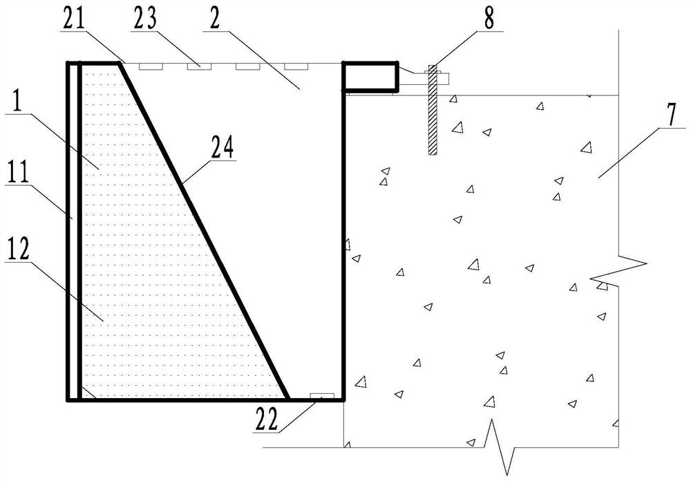
[0056] Such as image 3 , Figure 4 As shown, the anti-collision device of this embodiment is used for the anti-collision of the platform 7, and includes a force transmission assembly 1 and a water tank 2 containing a water medium inside; the force transmission assembly 1 includes a collision panel 11 and a The energy-dissipating material layer 12 on one side of the panel 11, the collision panel 11 is set on the side of the force transmission component 1 that receives the impact, and is composed of ultra-high-performance concrete and steel plates, and the energy-dissipating material layer 12 is polyurethane foam material. Between the collision panel 11 and the water tank 2 .

[0057] The water tank 2 includes a water tank roof 21 and a water tank wall 24, the water tank roof 21 is made of a superelastic material, the water tank 2 is closely connected with the force transmission component 1, and the water tank wall 24 at the connecting surface transmits force to the One side ...

Embodiment 3

[0063] Such as Figure 5 , Image 6 As shown, the anti-collision device of this embodiment is used for the anti-collision of the bearing platform 7, and includes a force transmission component 1 and a water tank 2 containing a water medium inside, and the water tank 2 is in the shape of a cylindrical barrel; The collision panel 11 and the energy-dissipating material layer 12 connected to the side of the collision panel 11, the collision panel 11 is arranged on the side of the force transmission component 1 that receives the impact, and is composed of ultra-high performance concrete and steel plates. The energy-dissipating material The layer 12 is made of polyurethane foam, which is arranged between the collision panel 11 and the water tank 2; the bottom of the force transmission component 1 is provided with a rotary paddle 9, which is connected to the water tank 2, and a rotatable rotating rod 10 is provided. , made of composite material board with good durability; there are ...


PUM


Abstract

The invention discloses an anti-collision device utilizing water media to consume energy, the anti-collision device mainly comprises a force transmission assembly and a water sump, and in addition, a light permeable tank and other related auxiliary energy consumption measures are arranged at the bottom of the force transmission assembly. A head-on collision panel is arranged on the outer side of the force transmission assembly, and the force transmission assembly comprises a light energy consumption material, an energy consumption framework and the like for cooperative energy consumption. The water sump is made of an ultrahigh-elasticity material and is provided with a drain hole with a damping effect and a water inlet hole. Compared with a traditional anti-collision device, the anti-collision device has the biggest characteristics that water media are used for energy consumption, self-resetting can be achieved after collision, the anti-collision device does not need to be maintained through manual measures, the energy consumption mode is environmentally friendly, the water media participating in energy consumption can be continuously obtained, the energy consumption capacity is high, and the safety of a protection object and an impacting object can be guaranteed; the problem that a traditional anti-collision device needs a large amount of manpower and material resources for maintenance and replacement after collision is solved.

Description

technical field [0001] The invention belongs to the technical field of anti-collision, and in particular relates to an anti-collision device utilizing water medium to consume energy. Background technique [0002] In the design of wading bridges, docks, and ships, anti-collision design is often required. Conventional anti-collision devices include steel structure anti-collision facilities, composite (FRP, etc.) material anti-collision facilities, and some composite structure anti-collision facilities. The plastic deformation of the protective device, material fracture, etc. dissipate energy. Such as: steel fenders, which are mainly composed of vertical outer plates, horizontal and vertical stiffening steel plates or other steel components through welding; during the collision process, the deformation and fracture of steel components are mainly used to dissipate the kinetic energy of the impact. [0003] This type of steel fender was widely used as anti-collision devices in b...

Claims


Application Information

Patent Timeline
IPC IPC(8): E01D19/00E02B3/26
CPCE01D19/00E02B3/26Y02A30/30
Inventor 樊伟孙文彪谢瑞洪吴青霖邵旭东
Owner HUNAN UNIV
Why Eureka
Try Eureka