
Under-pressure composite well drilling device and technology for deep high-temperature well

A high-temperature well and deep-seated technology, which is applied in drilling equipment, earthwork drilling, wellbore flushing, etc., can solve the problems of poor rock-breaking effect, low rock-breaking efficiency, and high rock hardness in hard rock

Pending Publication Date: 2021-07-30
BEIJING INST OF EXPLORATION ENG
View PDF0 Cites 0 Cited by
  • Summary
  • Abstract
  • Description
  • Claims
  • Application Information

AI Technical Summary

Problems solved by technology

[0002] In the process of exploration and development of deep earth resources, drilling is the most effective means to obtain underground physical data and establish production channels. Difficulties such as insufficient power at the bottom of the well have seriously affected the progress of exploration and development
At present, the commonly used method of rock breaking is rotary drilling with rotary table or compound drilling with screw drilling tools. However, as the hole depth increases, the supporting pressure of the drilling tool gradually increases, and the power transmitted from the rotary table to the bottom of the well is insufficient. Screw or turbo drilling tools are used to break rocks. It can only provide rotary power during the rock-breaking process, and the rock-breaking effect on hard rock is not good.

Method used


Image

  • Under-pressure composite well drilling device and technology for deep high-temperature well
  • Under-pressure composite well drilling device and technology for deep high-temperature well
  • Under-pressure composite well drilling device and technology for deep high-temperature well

Examples


Embodiment Construction

[0037] The following will clearly and completely describe the technical solutions in the embodiments of the present invention with reference to the accompanying drawings in the embodiments of the present invention. Obviously, the described embodiments are only some, not all, embodiments of the present invention. Based on the embodiments of the present invention, all other embodiments obtained by persons of ordinary skill in the art without making creative efforts belong to the protection scope of the present invention.

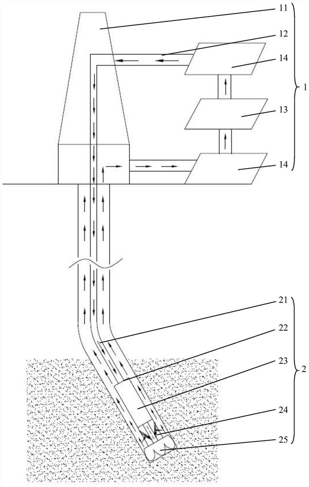
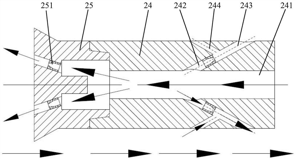
[0038] See attached figure 1 And attached figure 2 , the embodiment of the present invention discloses an underpressure composite drilling device for deep high-temperature wells, including:

[0039] The surface drilling unit 1; the ground drilling unit 1 includes a drilling rig 11, a drilling fluid cooling system 13 connected to the drilling rig 11 through a circulation pipeline 12, and a drilling fluid circulation system 14 located on both sides of the dril...


PUM


Abstract

The invention discloses an under-pressure composite well drilling device and technology for a deep high-temperature well. A ground drilling part comprises a drilling machine, a drilling fluid cooling system and drilling fluid circulating systems; an underground drilling tool part comprises a drill rod, a drill collar, a power assembly, a near-bit pressure reduction short section and a drill bit; the near-bit pressure reduction short section is provided with an annular channel; a plurality of suction flow channels are uniformly formed in the circumferential direction of the annular channel; sand mixing throat pipes communicating with the suction flow channels are arranged on the outer side wall of the near-bit pressure reduction short section in the circumferential direction; the outer side wall of the near-bit pressure reduction short section is further provided with pumping and suction flow channels; and the pumping and suction flow channels communicate with the nodes of the suction flow channels and the sand mixing throat pipes. According to the invention, the combined action of three modes of impact, rotation and thermal cracking is comprehensively utilized to destroy rocks at the bottom of a well, the near-bit pressure reduction short section generates local negative pressure in the annular channel at a near-bit position, and a drilling fluid which is just sprayed out of an energy-gathered nozzle to impact the bottom of the well and then carries rock debris to move up to the ground is sucked, so that the positive pressure difference at the bottom of the well is reduced, and the hold-down effect is reduced.

Description

technical field [0001] The invention relates to the technical fields of vertical wells, directional wells and horizontal wells, and more specifically relates to an underpressure composite drilling device and technology for deep high-temperature wells. Background technique [0002] In the process of exploration and development of deep earth resources, drilling is the most effective means to obtain underground physical data and establish production channels. Difficulties such as insufficient power at the bottom of the well have seriously affected the progress of exploration and development. At present, the commonly used method of rock breaking is rotary drilling with rotary table or compound drilling with screw drilling tools. However, as the hole depth increases, the supporting pressure of the drilling tool gradually increases, and the power transmitted from the rotary table to the bottom of the well is insufficient. Screw or turbo drilling tools are used to break rocks. It ...

Claims


Application Information

Patent Timeline
IPC IPC(8): E21B7/00E21B21/00E21B21/06
CPCE21B7/00E21B21/00E21B21/06E21B21/065
Inventor 翁炜吴烁贺云超冯美贵张德龙李晓东赵志涛张培丰杨鹏徐军军郭强欧阳志勇蒋睿史新慧
Owner BEIJING INST OF EXPLORATION ENG
Learn More