
Combined positioning method of inspection robot

A patrol robot and combined positioning technology, applied in the field of patrol robots, can solve the problem of high cost

Pending Publication Date: 2021-07-30
深圳亿嘉和科技研发有限公司
View PDF1 Cites 0 Cited by
  • Summary
  • Abstract
  • Description
  • Claims
  • Application Information

AI Technical Summary

Problems solved by technology

Single-point GNSS is cheap and easy to use, but its positioning accuracy is at the meter level; carrier phase difference technology (RTK) positioning accuracy can reach the centimeter level, but the cost is usually high, and additional deployment of base stations and human participation in regular maintenance are required

Method used


Image

  • Combined positioning method of inspection robot
  • Combined positioning method of inspection robot
  • Combined positioning method of inspection robot

Examples


Embodiment Construction

[0061] The present invention will be further explained below in conjunction with the accompanying drawings and specific embodiments.

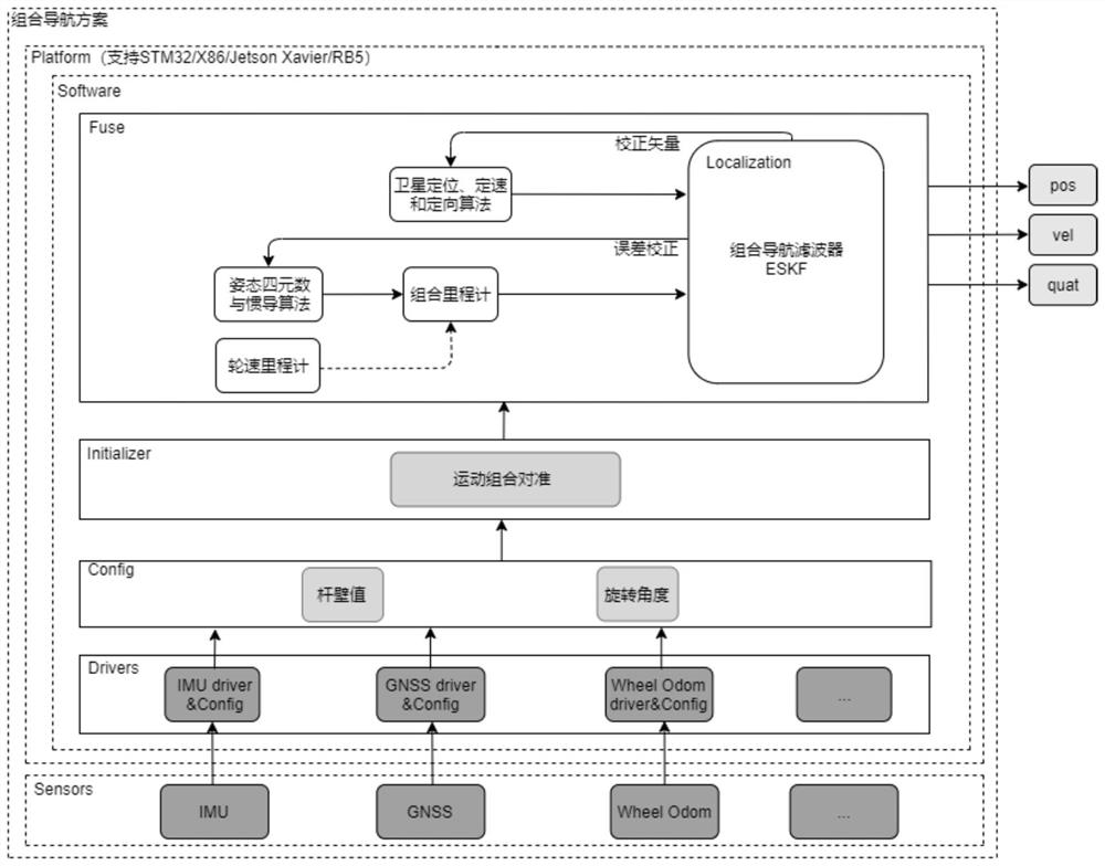
[0062] figure 1 It is a design diagram of the combined positioning software and hardware architecture of the inspection robot of the present invention. Such as figure 1 As shown, the combined positioning method of the substation inspection robot of the present invention comprises the following steps:

[0063] Step 1. Install inertial sensors and RAC sensors on the inspection robot, install a wheel speedometer on the chassis of the inspection robot, set an RTK mobile station on the inspection robot, and configure an RTK base station to communicate with the RTK mobile station through frequency modulation signals , complete RTK differential positioning through RTK mobile station;

[0064] Among them, the inertial sensor is a mature inertial sensor that has completed the calibration and temperature compensation of the turntable on the market; an...


PUM


Abstract

The invention discloses a combined positioning method of an inspection robot, which comprises the following steps of: (1) installing an inertial sensor and an RAC sensor on the inspection robot, and installing a wheel speed meter on a chassis of the inspection robot; (2) enabling the inspection robot to move at a constant speed, and acquiring data of the inertial sensor, the RAC sensor and the wheel speed meter in real time; and (3) respectively taking a a robot movement speed collected by the wheel speed meter and the robot position information obtained by the RAC sensor as error observed quantities, constructing a Kalman filter based on the error state quantity, and finally achieving combined positioning of the inspection robot. According to the combined positioning method of the inspection robot, low-cost and decimeter-level positioning precision is adopted to solve the problem that the positioning performance of a laser radar is reduced under some extreme working conditions, and the positioning stability of an inspection robot system is further improved.

Description

technical field [0001] The invention relates to the field of inspection robots, in particular to a combined positioning method for an inspection robot. Background technique [0002] Substation scene inspection robot needs to obtain navigation information such as its own pose and posture in real time when performing inspection work. Due to the rich texture of substation scene features, lidar is usually used as the main positioning method. However, in the substation scene, there will be extreme scenes with few or similar features such as long corridors, and severe weather such as rain and snow. At this time, the positioning performance of lidar will be greatly reduced or even impossible to locate. In response to this problem, sensors with complementary characteristics such as inertial measurement unit (inertial measurement unit, imu), wheel speed odometer, and global navigation satellite system (Global Navigation Satellite System, GNSS) are used for fusion to improve the posi...

Claims


Application Information

Patent Timeline
Patent Type & Authority Applications(China)
IPC IPC(8): G01C21/00G01C21/16G01C21/18G01S19/41G01S19/39G01S19/43G01S19/45G01S19/47
CPCG01C21/005G01C21/165G01C21/18G01S19/41G01S19/393G01S19/43G01S19/45G01S19/47
Inventor 程敏徐伟罗作煌刘文博李奇朱超闫宗涛李勇兵郭永春
Owner 深圳亿嘉和科技研发有限公司
Learn More