Single-power-source high-low-pressure self-adaptive high-precision dynamic and static loading test system

A single power source, loading test technology, applied in the direction of applying stable tension/pressure to test material strength, strength characteristics, instruments, etc., can solve the problem of limited output load accuracy, inability to load with high precision, minimal static load and dynamic load coupling , low precision and other issues

Active Publication Date: 2021-07-30
SHANDONG UNIV
View PDF15 Cites 2 Cited by
  • Summary
  • Abstract
  • Description
  • Claims
  • Application Information

AI Technical Summary

Problems solved by technology

The disadvantage is that due to mechanical transmission, it is difficult to achieve large tonnage loading
[0006] (2) The electro-hydraulic test system belongs to the testing machine with hydraulic transmission. Its power is realized by controlling the servo motor to drive the hydraulic two-way pump. The disadvantage is that, limited by the servo pressure regulation structure and technology, the accuracy of the output load is limited. When the large tonnage load is loaded, the accuracy is acceptable, and when the e

Method used


Image

  • Single-power-source high-low-pressure self-adaptive high-precision dynamic and static loading test system
  • Single-power-source high-low-pressure self-adaptive high-precision dynamic and static loading test system
  • Single-power-source high-low-pressure self-adaptive high-precision dynamic and static loading test system

Examples


Embodiment Construction

[0039] It should be pointed out that the following detailed description is exemplary and intended to provide further explanation to the present application. Unless defined otherwise, all technical and scientific terms used herein have the same meaning as commonly understood by one of ordinary skill in the art to which this application belongs.

[0040]It should be noted that the terminology used here is only for describing specific implementations, and is not intended to limit the exemplary implementations according to the present application. As used herein, unless the context clearly dictates otherwise, the singular is intended to include the plural, and it should also be understood that when the terms "comprising" and / or "comprising" are used in this specification, they mean There are features, steps, operations, means, components and / or combinations thereof.

[0041] As introduced in the background technology, none of the existing test systems can rely on a single power s...


PUM


Abstract

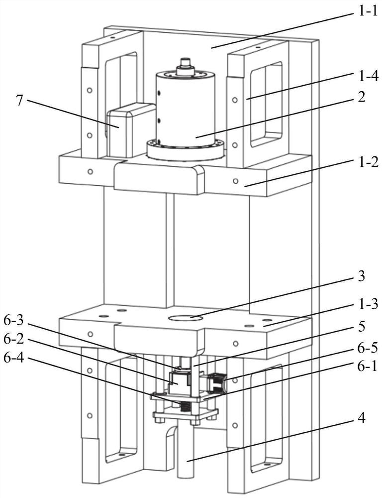
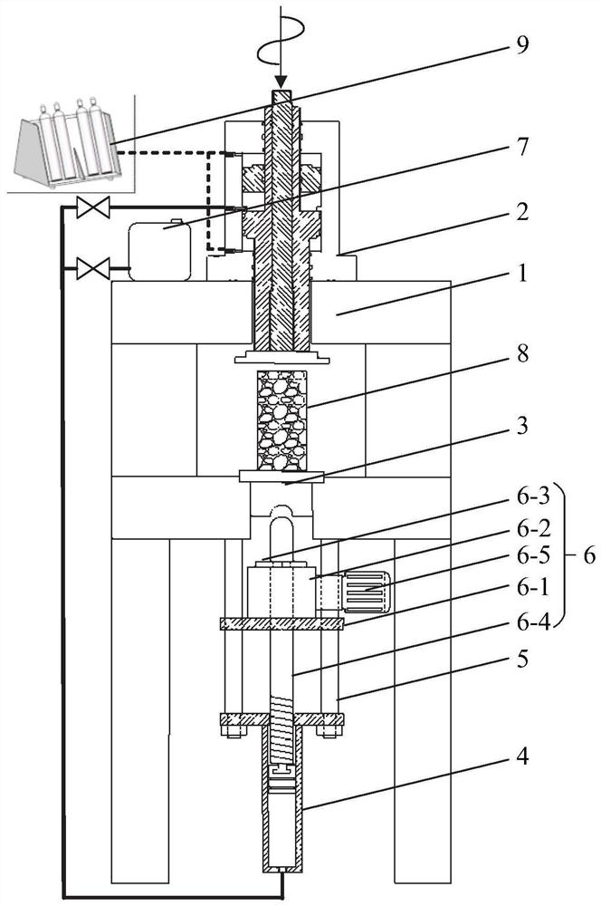
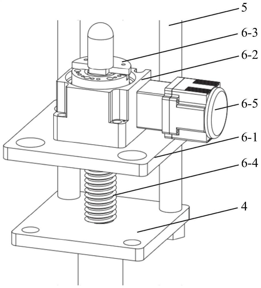
The invention relates to a single-power-source high-low-pressure self-adaptive high-precision dynamic and static loading test system which comprises a counter-force frame, a dynamic and static composite loading oil cylinder, a pressure-bearing jacking cover, a driving oil cylinder, a connecting rod, a power module and an oil tank. All parts of the counter-force frame are connected through mortise and tenon structures, borne acting force can be converted into pulling force of the front plate and the rear plate, and ultrahigh counter-force bearing is achieved. A return stroke cavity, an oil pressure cavity and an energy storage cavity are sequentially formed in the inner space of a cylinder body of the dynamic and static combined loading oil cylinder, a hollow loading rod is arranged in the cylinder body, an impact rod is movably arranged in the hollow loading rod, and combined loading of dynamic load, static load and disturbance load of different strain rates can be achieved. The power module comprises a sliding rail block, a wave tooth, a lead screw fixing flange, a lead screw and a servo motor, torque generated by the servo motor can be converted into vertical movement and vertical force of the lead screw, and original power is provided for the whole system. The vertical movement of the power module can realize high-precision minimum static load loading; the power module is matched with the dynamic and static combined loading oil cylinder, so that high-precision super-large static loading and dynamic and static coupling loading can be realized. According to the test device, random switching between high-precision extremely-small static load and dynamic load coupling loading and high-precision ultra-large static load and dynamic load coupling loading can be achieved by means of a single power source.

Description

technical field [0001] The invention relates to the technical field of test equipment, in particular to a single power source high and low pressure adaptive high-precision dynamic and static loading test system. Background technique [0002] The statements herein merely provide background information related to the present invention and do not necessarily constitute prior art. [0003] In the fields of material science and rock mechanics, the mechanical and dynamic properties of concrete, rock, and rock-like materials need to be obtained by using the mechanical test system to carry out stress-strain static tests and pre-static load impact disturbance dynamic-static coupling tests. In order to ensure the test accuracy, the test has the following requirements for the mechanical test system: (1) The static load loading accuracy of the mechanical test system is high, generally not higher than 1% of the measuring range. (2) The static load loading capacity of the mechanical test...

Claims


Application Information

Patent Timeline
IPC IPC(8): G01N3/14G01N3/307G01N3/02
CPCG01N3/14G01N3/307G01N3/02G01N2203/001G01N2203/0033
Inventor 王汉鹏张冰李梦天王鹏于欣平
Owner SHANDONG UNIV
Why Eureka
Try Eureka