
Diaphragm type electromagnetic track vibration energy recovery system

A vibration energy recovery and vibration energy harvesting technology, which is applied to electric vehicles, piezoelectric effect/electrostrictive or magnetostrictive motors, generators/motors, etc., can solve the problem of low life and low output power of piezoelectric materials , Excessive reluctance of the magnetic circuit, etc., to achieve the effect of preventing friction and collision, improving efficiency and reducing reluctance

Inactive Publication Date: 2021-07-30
SHANGHAI UNIV OF ENG SCI
View PDF8 Cites 1 Cited by
  • Summary
  • Abstract
  • Description
  • Claims
  • Application Information

AI Technical Summary

Problems solved by technology

Among them, although the structure of the piezoelectric conversion is relatively simple, the life of the piezoelectric material is not long and it is easy to be damaged; although the structure of the electromagnetic conversion is relatively complicated, it has the advantages of not being limited by the performance of the material, strong environmental adaptability and high reliability.
However, the current electromagnetic track vibration energy recovery system fails to achieve a good electromagnetic induction effect. The main reason is that the reluctance in the magnetic circuit is too large, resulting in a decrease in output power.

Method used


Image

  • Diaphragm type electromagnetic track vibration energy recovery system
  • Diaphragm type electromagnetic track vibration energy recovery system
  • Diaphragm type electromagnetic track vibration energy recovery system

Examples


Embodiment

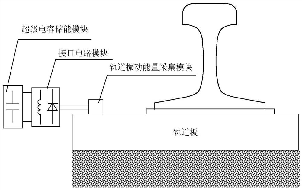
[0028] like figure 1 As shown, the present invention relates to a diaphragm type electromagnetic orbital vibration energy recovery system, which is mounted on a track panel between the sleeper and the Tao bed, including the track vibration energy acquisition module, an interface circuit module, and a supercapacitive energy storage module. The track vibration energy acquisition module, the interface circuit module and the supercapacitor energy storage module are sequentially connected.

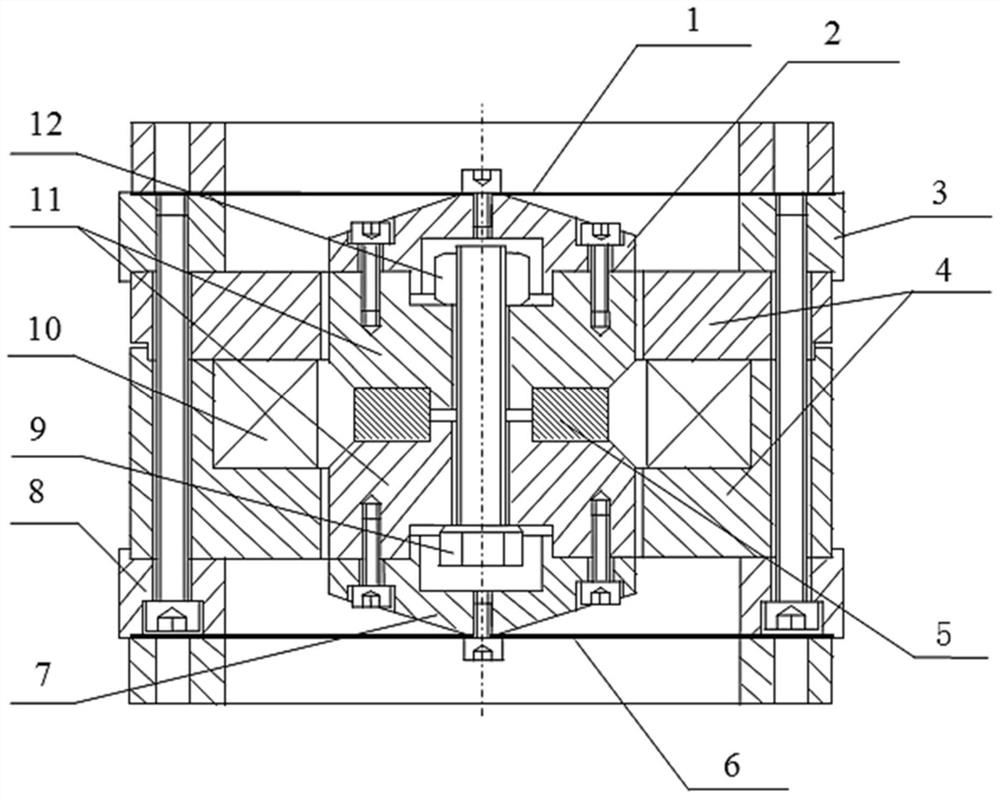
[0029] The track vibration energy acquisition module is a shaft symmetrical structure, such as figure 2 Indicated. The module includes a housing, an upper film spring 1, an upper cone 2, a upper press ring 3, a ferrule 4, a ring magnet 5, a lower film spring 6, a lower circular cone 7, a lower pressure ring 8, a bolt 9 , Coil 10, magnetic pole 11, and nut 12. The upper cone 2, the iron yoke 4, the annular magnet 5, the lower film spring 6, the lower circular cone 7, the wearing bolt 9, the coil 10,...


PUM


Abstract

The invention relates to a diaphragm type electromagnetic track vibration energy recovery system which is arranged on a track plate. The system comprises a track vibration energy collection module, an interface circuit module and a super capacitor energy storage module which are connected in sequence; the track vibration energy collection module comprises a shell, an upper pressing ring (3) and a lower pressing ring (8) which are respectively installed at the top and the bottom of the shell, an upper diaphragm spring (1) which is arranged at the bottom of the upper pressing ring (3), a lower diaphragm spring (6) which is arranged at the bottom of the lower pressing ring (8), and a movable magnet assembly which is arranged between the upper pressing ring (3) and the lower pressing ring (8). Compared with the prior art, the invention has the advantages of large diaphragm spring deformation displacement, high magnetic circuit closing electromechanical energy conversion efficiency, broadening of the response frequency band of the track vibration energy acquisition module and the like.

Description

Technical field [0001] The present invention relates to the field of rail environments vibration energy recovery, in particular, to a diaphragm type electromagnetic orbital vibration energy recovery system. Background technique [0002] At present, the track wireless monitoring sensing node has put forward greater demand for small power power supplies, and environmental vibration energy recovery has become a technical approach that has developed potential. The high-speed driving of the rail vehicle, the incompatibility of the track and the wheel surface inconsistency will incentive and induce strong vibration of the orbit. Therefore, by recovering the rail vibration energy, the rail wireless monitoring sensing node can be achieved. The mechanical energy of the track vibration is currently converted into electrical energy, and two methods of electrical conversion and electromagnetic conversion. Among them, although the piezoelectric conversion is simpler, the pressure material is ...

Claims


Application Information

Patent Timeline
Patent Type & Authority Applications(China)
IPC IPC(8): H02N2/18H02J7/32
CPCH02N2/186H02J7/32
Inventor 袁天辰杨俭宋瑞刚杨沥宰道生
Owner SHANGHAI UNIV OF ENG SCI
Learn More