Optical imaging lens

An optical imaging lens and lens technology, applied in optics, optical components, instruments, etc., can solve problems such as poor optical performance

Active Publication Date: 2021-08-03
ZHEJIANG SUNNY OPTICAL CO LTD
View PDF11 Cites 3 Cited by
  • Summary
  • Abstract
  • Description
  • Claims
  • Application Information

AI Technical Summary

Problems solved by technology

[0004] The main purpose of the present invention is to provide an optical imaging lens to solve the problem of poor optical performance of the optical imaging lens in the prior art

Method used


Image

  • Optical imaging lens
  • Optical imaging lens
  • Optical imaging lens

Examples


Embodiment 1

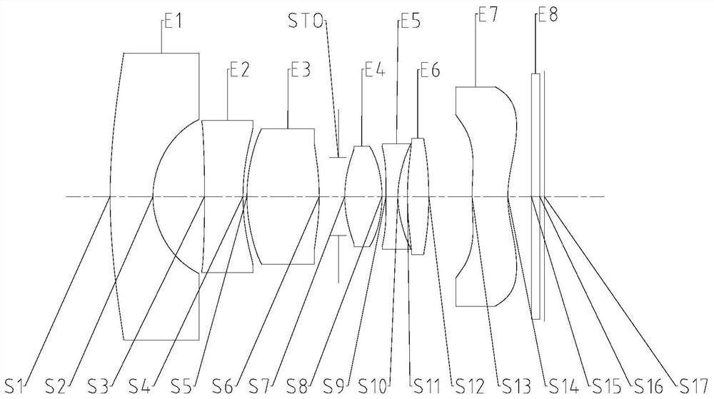
[0076] Such as Figure 1 to Figure 40 As shown, the optical imaging lens sequentially includes a first lens E1, a second lens E2, a third lens E3 with positive refractive power, a fourth lens E4 with positive refractive power, and a fifth lens along the optical axis from the object side to the image side E5, sixth lens E6 and seventh lens E7 with negative power. The image side S6 of the third lens is a convex surface; half of the maximum field of view angle of the optical imaging lens Semi-FOV meets: 70°1.7; Between the air gap T34 between the third lens and the fourth lens on the optical axis, the air gap T45 between the fourth lens and the fifth lens on the optical axis, and the central thickness CT4 of the fourth lens on the optical axis Satisfy: 0.5<(T34+T45) / CT4<1.0; between the effective focal length f1 of the first lens and the effective focal length f4 of the fourth lens satisfies: -1.0<f4 / f1<-0.5.

[0077] Preferably, 75.0°≦Semi-FOV≦75.6°.

[0078]Preferably, 1.7

Embodiment 2

[0097] The optical imaging lens includes a first lens E1, a second lens E2, a third lens E3 with positive refractive power, a fourth lens E4 with positive refractive power, a fifth lens E5, and a first lens from the object side to the image side along the optical axis. The six lenses E6 and the seventh lens E7 with negative refractive power, the image side of the third lens is convex. Half the Semi-FOV of the maximum viewing angle of the optical imaging lens satisfies: 70°1.7; the third lens and the third lens The air interval T34 of the four lenses on the optical axis, the air interval T45 of the fourth lens and the fifth lens on the optical axis, and the central thickness CT4 of the fourth lens on the optical axis satisfy: 0.5<(T34+T45) / CT4<1.0; between the entrance pupil diameter EPD of the optical imaging lens, the maximum effective radius DT32 on the image side of the third lens, and the maximum effective radius DT41 on the object side of the fourth lens: 0.6<2×EPD / (DT32...


PUM


Abstract

The invention provides an optical imaging lens. The optical imaging lens sequentially comprises, from an object side to an image side along an optical axis, a first lens, a second lens, a third lens with positive focal power, wherein the image side surface of the third lens is a convex surface, a fourth lens with positive focal power, a fifth lens, a sixth lens, and a seventh lens with negative focal power, wherein half of the maximum field-of-view semi-FOV of the optical imaging lens meets the following condition: Semi-FOV is greater than 70 degrees and less than 90 degrees; the maximum value Namx of the refractive indexes of the first lens to the seventh lens meets the condition that Namx is greater than 1.7; the air interval T34 between the third lens and the fourth lens on the optical axis, the air interval T45 between the fourth lens and the fifth lens on the optical axis and the central thickness CT4 of the fourth lens on the optical axis meet the following condition: (T34 + T45) / CT4 is greater than 0.5 and less than 1.0; and the effective focal length f1 of the first lens and the effective focal length f4 of the fourth lens meet the condition that f4 / f1 is greater than -1.0 and less than -0.5. The problem that an optical imaging lens in the prior art is poor in optical performance is solved.

Description

technical field [0001] The present invention relates to the technical field of optical imaging equipment, in particular to an optical imaging lens. Background technique [0002] With the continuous development of science and technology, people's safety awareness is also constantly improving. More and more places will use security monitoring, and the requirements for corresponding optical imaging equipment are also getting higher and higher. Since the optical imaging lenses used in the security monitoring field have high requirements for capturing objects within a limited shooting range, people often choose to use wide-angle lenses with a larger field of view. Wide-angle lens, also known as short lens, is basically characterized by a larger angle of view and a wider field of view. The range of scenery observed from a certain point of view is much larger than that seen by the human eye at the same point of view; the depth of field is long, and it can show considerable The cle...

Claims


Application Information

Patent Timeline
IPC IPC(8): G02B13/00G02B13/06G02B13/18
CPCG02B13/0045G02B13/06G02B13/18
Inventor 黄景鑫宋立通龚停停戴付建赵烈烽
Owner ZHEJIANG SUNNY OPTICAL CO LTD
Why Eureka
Try Eureka