Electronic equipment optical part research and development cooling device

A technology for electronic equipment and cooling devices, which is applied in the field of R&D cooling devices for optical components of electronic equipment, can solve problems such as cooling blind spots, affecting product quality, and prone to scratches, so as to avoid cooling blind spots, improve cooling efficiency, and improve processing efficiency effect

Active Publication Date: 2021-08-06
扬州辰亚光学科技有限公司
12 Cites 1 Cited by

AI-Extracted Technical Summary

Problems solved by technology

[0005] 1. Although the device has improved the placement of the lens, there are still cooling blind spots, low cooling efficiency, and prone to secondary rework cooling caused by uneven cooling
[0006] 2. The device uses a...

Method used

Described frame 1 bottom wall lower surface is fixedly installed with the outside of opening 6 near the outer side of opening 6, and the middle part of the upper surface of the described frame 7 is fixedly equipped with guide rail 10, and slide block 9 is placed in the described guide rail 10, A movable plate 8 is fixedly installed on the top of the slider 9, a rubber pad a12 is fixedly installed on the upper surface of the movable plate 8, and the rubber pad a12 is located directly below the port 19, and the upper surface of the bottom wall of the shaped plate 7 is close to The front and rear sides of the guide rail 10 are fixed with limit blocks 11, and there are four sets of limit blocks 11. Support plates 5 are fixedly installed on the left and right sides of the lower surface of the bottom wall of the frame 1, which can be cooled by the atomizer 3. The water is atomized and blown into the box body 2, and the drive shaft of the drive motor 17 drives the fan blade 18 to rotate, forming a negative pressure exhaust air and mist exhaust channel, so that the air containing atomized water is exhausted to the inner limit of the port 19 On the lens workpiece, this method replaces the existing direct water spraying, so as to avoid excessive impact of the spray water on the workpiece, effectively ensure the quality of the lens workpiece, improve the safety factor of the device, and enter the air through the set through pipe 4 to ensure smooth air ventilation. A splint 23 and a spring 24 are provided, and the disc lens is placed longitudinally between two sets of splints 23. The tension of the spring 24 can push the sleeve 20 to move inward. Full contact can improve the cooling efficiency of the workpiece to a certain extent, and this positioning method is convenient for the disassembly and assembly of the workpiece, and indirectly improves the processing efficiency. By setting the limit block 11 and the movable plate 8, the movable plate 8 can be fitted during clamping and positioning. The limit block 11 on the rear side, and the splint 23 is located in the middle of the disc lens workpiece. Due to the concentric arrangement of the lens and the splint 23, the movable plate 8 can be moved forward, and the movable plate 8 can be in contact with the transparent arc surface of the disc. The rubber pad a12 drives the disc to rotate until the movable plate 8 is attached to the limit block 11 on the front side, and the transparent workpiece rotates 180 degrees, so that the arc surface of the disc lens on the lower side is placed upwards to ensure that the disc The lens is completely cooled to avoid cooling blind spots.
During use, atomizer 3 and driving motor 17 are respectively externally connected to power supply, and the staff carries out opening and closing control by its own switch, cooling water c...

Abstract

The invention relates to the technical field of optical parts, and discloses an electronic equipment optical part research and development cooling device. The electronic equipment optical part research and development cooling device comprises a frame, a box body is fixedly installed at the top in the frame, an atomizer is fixedly installed in the middle of the upper surface of the frame, and an air outlet pipe of the atomizer communicates with the box body. A water supply tank is integrally formed at the top of the atomizer, an air guide pipe is arranged at the bottom of the box body in a communicating mode, a negative pressure pipe is arranged in the middle of the air guide pipe in a communicating mode, and a driving motor is fixedly installed in the middle in the negative pressure pipe through a support. According to the electronic equipment optical part research and development cooling device, by arranging clamping plates and a spring, a wafer lens is longitudinally arranged between the two sets of clamping plates, a sleeve can be pushed to move inwards through the tension of the spring, a workpiece is longitudinally fixed through the clamping plates, the workpiece makes full contact with cooling air and atomized water, the workpiece cooling efficiency can be improved to a certain degree, the workpiece can be conveniently disassembled and assembled through the positioning mode, and the processing efficiency is indirectly improved.

Application Domain

Lighting and heating apparatusCooling fluid circulation

Technology Topic

PhysicsElectric machinery +3

Image

  • Electronic equipment optical part research and development cooling device
  • Electronic equipment optical part research and development cooling device
  • Electronic equipment optical part research and development cooling device

Examples

  • Experimental program(1)

Example Embodiment

[0028] In order to make the techniques, creative features, objective and efficacy of the present invention, and the embodiments are further illustrated in connection with the specific embodiments.
[0029] In the description of the present invention, it is to be understood that the terms "upper", "lower", "front", "post", "left", "right", "top", "bottom", "inside", " The orientation or positional relationship of the instructions such as "is based on the orientation or positional relationship shown in the drawings, which is merely description of the present invention and simplified description, rather than indicating or implying that the device or component must have a specific direction. Specific orientation construction and operation, it is not understood to be limited to the present invention; in the description of the invention, it is to be explained, unless otherwise specified and defined, the term "installation", "connected", "set" should be To make a broad understanding, for example, it can be fixed, setting, or a detachable connection, setting, or integral connection, setting. The specific meaning of the above terms in the present invention will be appreciated to those skilled in the art.
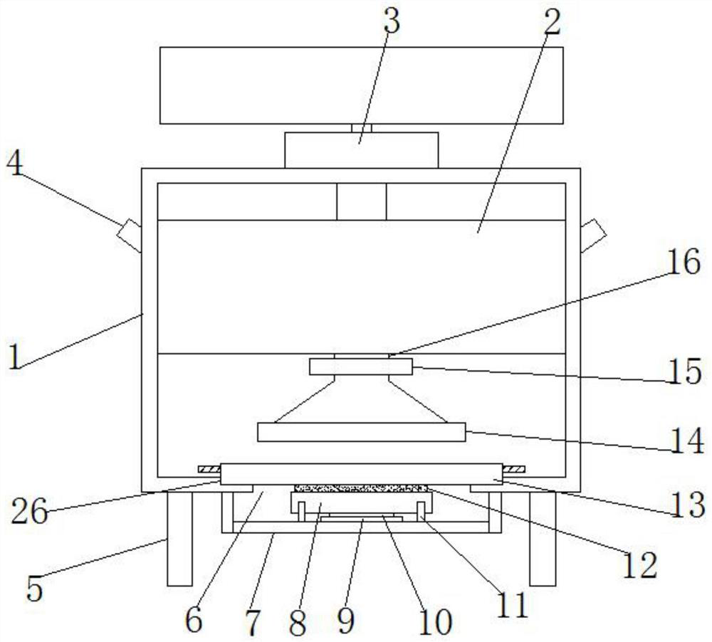
[0030] See Figure 1-5 The present invention provides a technical solution: an electronic device optical component develops a cooling device, including a frame 1;
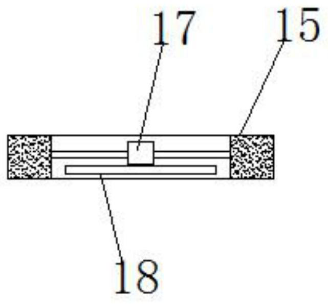
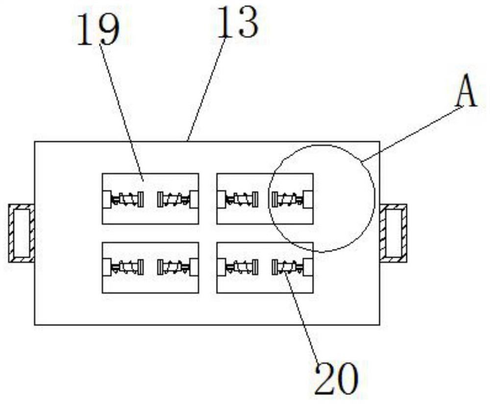
[0031] The casing 2 is attached to the top of the frame 1, and the upper surface of the frame 1 is fixedly mounted, and the outlet tube of the atomizer 3 is in communication with the casing 2, the atomizer 3. The top integration is provided with a water supply box, and the bottom of the casing 2 communicates with a vapor pipe 16, and a negative pressure pipe 15 is connected in communication, and the middle portion of the negative pressure tube 15 is fixedly mounted by the stent. The drive motor 17, the drive shaft bottom of the drive motor 17 drives a fan blade 18, and the venting pipe 16 is connected to the bottom of the wind cover 14, and the shroud 14 is placed inwardly, the frame 13, the frame The upper portion of the bottom wall is opened 6, and the surface of the frame 1 is opened to the left and right sides of the opening 6 on the upper left side of the opening 6, and the retail plate 13 is placed in the recess 26, and the central portion in the middle is opened. There are four groups in the port 19, and there are four groups in each group, and each group is placed on both sides of the left and right sides of the sleeve 20, and the outer wall of the sleeve 20 penetrates the six rod 21, and the six rod 21 Extended to the sleeve 20, the outer end of the six rod 21 is rotated by the bearing 25 and the sleeve 20 and the sleeve 20 and the six-rod 21 are provided with a spring 24, and the sleeve 20 is fixed. The splint 23 is mounted, and the ladle 23 is fixedly mounted with a rubber pad B22;
[0032]The outer side surface of the frame 1 is attached to the outer side of the opening 6 near the opening 6, and the guide rail 10 is mounted in the upper surface of the flange 7, and the rail 10 is placed in the rail 10, the sliding The movable plate 8 is attached to the top of the block 9, and a rubber pad A12 is attached to the upper surface of the movable plate 8, and the rubber pad A12 is located directly below the port 19, and the upper surface of the plate 7 is close to the guide rail 10. The finishes 1 block 11 is fixed to both sides, and the limit block 11 has four groups, and the branch plate 5 is fixed to the left and right side of the surface of the frame 1, and the cooling water can be cooled by the atomizer 3. And blown into the casing 2, by rotating the fan blade 18 by the drive shaft of the drive motor 17, form a negative pressure exhaust fog passage, so that air containing atomized water to the inner limit lens workpiece On this way, replacing the existing direct water spray, so as not to prevent the workpiece, effectively ensure the quality of the lens workpiece, improve the safety factor of the device, enter the air through the set pipe 4 to ensure the fluid ventilation, by setting a splint 23 and the spring 24, the longitudinal direction of the wafer lens is placed between the two sets of clamp 23, and the sleeve 20 can be pushed through the spring 24 tension, and the workpiece is fixed longitudinally to make the workpiece and the cooling air and atomized water. The workpiece cooling efficiency can be improved to the degree of cooling efficiency, and the positioning method is convenient for the workpiece, indirectly holes the processing efficiency, by setting the finite block 11 and the movable plate 8, during the clamping positioning, the movable plate 8 is bonded to the rear side. The limit block 11 and the splint 23 is located in the middle of the wafer lens workpiece, since the concentric arrangement of the lens and the splint 23 can pass the front movement plate 8, the movable plate 8 can be in contact with the wafer transparent arc. Rubber pad. A12 drives the wafer to rotate until the movable plate 8 is brought into the limit block 11 on the front side, and the transparent workpiece generates 180 degrees to rotate, so that the arc of the wafer is placed on the lower side to ensure the disc. Complete, avoiding cooling blind zones.
[0033] In this embodiment (see figure 1 The tube 4 is provided with a through-line portion 4, and the tube 4 extends to the outer side of the frame 1, and the mounting of the web is fixedly mounted, and the air can be entered through the through pipe 4, and The filter prevents impurities from entering the box 2.
[0034] In this embodiment (see figure 2 ), The drive motor 17 is a waterproof motor to ensure stable operation of the motor, and ensure its service life.
[0035] In this embodiment (see Figure 5 The spring 24 is a stainless steel article, and the spring 24 is fixed to the pinch plate 23 and the retaining plate 13, respectively, and the stainless steel material can delay the spring rust and the fatigue speed, and the fixed connection prevents the spring 24 from falling off.
[0036] In this embodiment (see Figure 5 ), The outer shape of the six-rod 21 matches the through hole profile of the side wall of the sleeve 20, and the six rod 21 is bonded to the sleeve 20, and the sleeve 20 can be rotated, and the six rod 21 can be guaranteed. Synchronously rotate synchronously with the sleeve 20.
[0037] In this embodiment (see figure 1 and image 3 The outer portion of the outer outer wall in the outer wall is fixed to the middle of the outer wall of the outer wall, and the hand surface is opened, and the hand is turned into the panel 13, and the effluent is safe, and the friction can be guaranteed to prevent slippery.
[0038] In this embodiment (see image 3 ), The horizontal length of the inlet 19 is 10 cm, so that the opening 19 has sufficient operating space, making it easy to adjust the clamp picking workpiece.
[0039] When using an electronic device optical component, it is necessary to say that the present invention is an electronic device optical component development cooling device, including a frame 1, a case 2, an atomizer 3, and a through pipe 4. However, the branch 5, the opening 6, the flaps 7, the movable plate 8, the slider 9, the guide rail 10, the limit block 11, the rubber pad A12, the sheet 13, the wind cover 14, the negative pressure pipe 15, the air wind tube 16 The drive motor 17, the fan blade 18, the springs 19, the sleeve 20, the hexagonal rod 21, the rubber pad B22, the splint 23, the spring 24, the bearing 25, the recess 26, and the components are general standard parts or those skilled in the art. The components of aware of the knowledge, the structure and principles are known for the skilled personnel or by conventional experimental methods.
[0040] When using, the atomizer 3 and the drive motor 17 are respectively connected, and the staff can be opened through its own switch, and the cooling water can be atomized by the atomizer 3, and is blown into the casing 2, by the drive The drive shaft of the motor 17 rotates, forms a negative pressure ventilation spray passage, so that air containing atomized water is sent to the intensive lens workpiece, which replaces the existing direct water, To avoid over-impact workpieces, effectively ensure the quality of the lens workpiece, the safety factor of the device, enter the air through the set through the pipe 4 to ensure smooth air ventilation, by setting the splint 23 and the spring 24, vertical direction Between the two sets of splints 23, the spring 24 tension can be pushed through the sleeve 20, and the workpiece is fixed longitudinally, and the workpiece is sufficiently contacted with the cooling air and atomized water, and the workpiece cooling efficiency can be improved. The positioning method is convenient for the workpiece's disassembly, indirect improvement processing efficiency, by setting the finite block 11 and the movable plate 8, during the clamping positioning, the movable plate 8 is attached to the rear side block 11, and the splint 23 is located In the middle of the wafer lens workpiece, since the lens is arranged with the concentric arrangement of the pinch 23, the movable plate 8 can be rotated by the rubber pad A12 that is in contact with the wafer transparent arc, until the movable plate 8 The limit block 11 in the front side, the transparent workpiece generates 180 degrees to rotate, so that the circumferential lens is placed on the lower side of the arc to ensure that the waist lens cooling is complete, avoiding the cooling blind zone, cooling in the curve After the processing is completed, the clamping area cooling blind zone can be avoided by adjusting the clamping position of the workpiece.
[0041] The basic principles and main features of the present invention are shown and described above, and the advantages of the present invention will be described, and it is apparent to those skilled in the art, and In the case of feature, the present invention can be implemented in other specific forms. Therefore, in any case, it should be regarded as an exemplary, and non-limiting, and the scope of the invention is defined by the appended claims. Therefore, it is intended to fall in accordance with the claims All variations in the meaning and range of equivalents are included in the present invention. Any reference numerals in the claims should not be regarded as the claims.
[0042] In addition, it should be understood that although this specification describes in accordance with an embodiment, it is not to include only one independent technical solution. The description of the specification is simply, and those skilled in the art should use the specification as a whole. The technical solutions in each embodiment may also be appropriately combined to form another embodiments which will be appreciated by those skilled in the art.

PUM

PropertyMeasurementUnit
Horizontal length10.0cm

Description & Claims & Application Information

We can also present the details of the Description, Claims and Application information to help users get a comprehensive understanding of the technical details of the patent, such as background art, summary of invention, brief description of drawings, description of embodiments, and other original content. On the other hand, users can also determine the specific scope of protection of the technology through the list of claims; as well as understand the changes in the life cycle of the technology with the presentation of the patent timeline. Login to view more.

Similar technology patents

Air film cooling hole structure

ActiveCN106640216AImprove cooling efficiencyIncrease the export area
Owner:HEBEI UNIV OF TECH

Brake cooling method and brake cooling device

InactiveCN104859606AImprove cooling efficiencyavoid slippery roads
Owner:WEICHAI POWER CO LTD

Classification and recommendation of technical efficacy words

  • Easy to assemble and disassemble
  • Improve cooling efficiency

Method and device for controlling inverter compressor

InactiveCN101539151AImprove cooling efficiencyavoid overshoot
Owner:HAIER GRP CORP +1

Data center and cooling system thereof

Owner:HONGFUJIN PRECISION ELECTRONICS (TIANJIN) CO LTD

Process for preparing size-controllable nano-silicon dioxide

InactiveCN1546373AImprove cooling efficiencyprevent particle size increase
Owner:GUANGZHOU GBS HIGH TECH & IND
Why Eureka
Try Eureka