Welding and cutting equipment with protection function and application method thereof

A technology of cutting equipment and protection function, applied in the field of welding and cutting equipment, can solve the problems of poor wideness, difficult adjustment of the placement position of parts, easy to produce unfavorable high temperature conditions, etc., to achieve the effect of improving cutting effect and improving wideness

Inactive Publication Date: 2021-08-10
NANJING YUZHI INTELLIGENT TECH CO LTD
View PDF0 Cites 3 Cited by
  • Summary
  • Abstract
  • Description
  • Claims
  • Application Information

AI Technical Summary

Problems solved by technology

[0002] With the development of the modern mechanical processing industry, the requirements for cutting quality and precision are constantly improving, and the requirements for improving production efficiency, reducing production costs, and highly intelligent automatic cutting functions are also increasing. The development of CNC cutting machines must be To meet the requirements of the development of modern mechanical processing industry, cutting machines are divided into flame cutting machines, plasma cutting machines, laser cutting machines, water cutting, etc. Laser cutting machines have the fastest efficiency, highest cutting precision, and generally small cutting thickness. The cutting speed is also very fast, and the cutting surface has a certain slope. The flame cutting machine is aimed at thicker carbon steel materials. However, in the prior art, the overall size of the parts often appears in the process of welding parts. However, due to the structural limitation of the existing cutting equipment, the existing cutting equipment with a single specification can only perform the cutting processing of the same type of parts, which leads to poor practical use of the equipment. At the same time, under certain circumstances, the existing cutting equipment is prone to unfavorable high-temperature conditions during the cutting process, which will affect the actual cutting effect of the equipment. At the same time, it is easy to generate large noise and harmful smoke during the cutting process, which will effectively affect the health of the operator. At the same time, in the actual cutting process, due to the size of the parts, it is not easy to adjust the placement position of the parts, which leads to poor actual use of the equipment

Method used


Image

  • Welding and cutting equipment with protection function and application method thereof
  • Welding and cutting equipment with protection function and application method thereof
  • Welding and cutting equipment with protection function and application method thereof

Examples


Embodiment 1

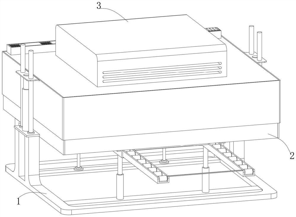
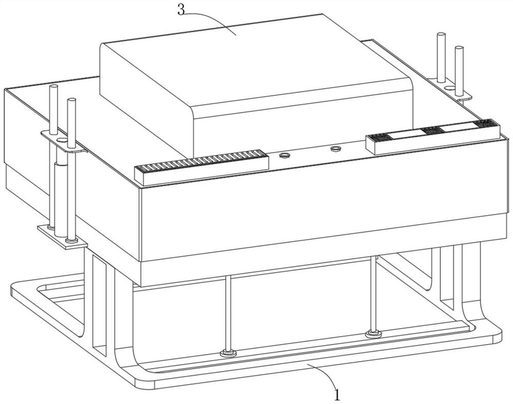
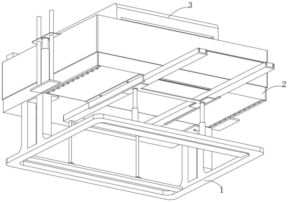
[0032] Embodiment one, with reference to Figure 1-9 : A welding and cutting equipment with protection function, comprising: a support mechanism 1, the support mechanism 1 includes a base 101, a bottom frame 102, two support parts and a lifting part, the establishment of the base 101 provides an installation basis for other functional parts of the equipment, The installation of other functional parts of the equipment is facilitated by the establishment of the bottom frame 102. The bottom frame 102 is fixedly connected to the top of the base 101, and the sound insulation frame 103 is fixedly connected inside the bottom frame 102. The establishment of the sound insulation frame 103 and the sound insulation board 202 can effectively prevent the equipment from The noise generated during actual use will have adverse effects on the operator. The two supporting parts are fixedly connected to the outer surfaces of both sides of the bottom frame 102, and the lifting part is arranged on ...


PUM


Abstract

The invention discloses welding and cutting equipment with a protection function and an application method thereof. The welding and cutting equipment comprises a supporting mechanism, wherein the supporting mechanism comprises a base, a bottom frame, two supporting parts and a lifting part; the bottom frame is fixedly connected to the top of the base; a sound insulation frame is fixedly connected to the interior of the bottom frame; and the two supporting parts are fixedly connected to the outer surfaces of the two sides of the bottom frame respectively. By controlling lifting of a third air pressure rod, the lifting part can conveniently take out and put back a positioning mechanism to the bottom frame, then to-be-treated parts are conveniently placed on the top of a carrying disc, and then the placement positions of the to-be-treated parts can be conveniently and effectively adjusted under rotary supporting of the carrying disc; and the first air pressure rod is controlled to move the actual use position of a pressing plate, then the pressing plate can effectively drive a linkage gear to rotate through a rack, and then under the driving of the linkage gear, a supporting shaft can drive a first threaded rod and a second threaded rod to effectively rotate through a first bevel gear and a second bevel gear.

Description

technical field [0001] The invention belongs to the technical field of cutting equipment, and in particular relates to a welding and cutting equipment with protection function and a using method thereof. Background technique [0002] With the development of the modern mechanical processing industry, the requirements for cutting quality and precision are constantly improving, and the requirements for improving production efficiency, reducing production costs, and highly intelligent automatic cutting functions are also increasing. The development of CNC cutting machines must be To meet the requirements of the development of modern mechanical processing industry, cutting machines are divided into flame cutting machines, plasma cutting machines, laser cutting machines, water cutting, etc. Laser cutting machines have the fastest efficiency, highest cutting precision, and generally small cutting thickness. The cutting speed is also very fast, and the cutting surface has a certain ...

Claims


Application Information

Patent Timeline
Patent Type & Authority Applications(China)
IPC IPC(8): B23D19/00B23D33/00B23D33/02B23Q11/00B23Q11/08B08B15/04
CPCB08B15/04B23D19/00B23D33/00B23D33/02B23Q11/0042B23Q11/0096B23Q11/08
Inventor 刘勇强程金强姜国建
Owner NANJING YUZHI INTELLIGENT TECH CO LTD
Why Eureka
Try Eureka