
Laser cutting mechanism

A laser cutting and end plate technology, applied in laser welding equipment, other manufacturing equipment/tools, welding equipment, etc., can solve the problems of manual position replacement, high cost of laser cutting process, and insufficient accuracy of manual positioning of sheet metal.

Pending Publication Date: 2021-08-10
张仁虎
View PDF0 Cites 0 Cited by
  • Summary
  • Abstract
  • Description
  • Claims
  • Application Information

AI Technical Summary

Problems solved by technology

[0002] With the development of industrial technology, modern sheet metal processing technology has become more and more perfect. In the past, sheet metal needs to be cut and bent during processing, but plasma or plasma is required to unload in the middle of sheet metal. Laser cutting, in the past industrial level, most cases use plasma cutting, the accuracy of laser cutting is relatively high, but the process cost of laser cutting is also high;
[0003] The area and weight of the sheet metal are relatively large, and the loading and unloading of the sheet metal material is laborious, and the accuracy of manual positioning of the sheet metal is not high enough, and it is necessary to replace multiple stations during the processing of the sheet metal. The work station is troublesome and wastes a lot of manpower

Method used


Image

  • Laser cutting mechanism
  • Laser cutting mechanism
  • Laser cutting mechanism

Examples


Embodiment Construction

[0027] In order to make the object, technical solution and advantages of the present invention clearer, the present invention will be further described in detail below in conjunction with the accompanying drawings and embodiments. It should be understood that the specific embodiments described here are only used to explain the present invention, not to limit the present invention.

[0028] In describing the present invention, it should be understood that the terms "longitudinal", "transverse", "upper", "lower", "front", "rear", "left", "right", "vertical", The orientations or positional relationships indicated by "horizontal", "top", "bottom", "inner", "outer", etc. are based on the orientations or positional relationships shown in the drawings, and are only for the convenience of describing the present invention, rather than indicating or It should not be construed as limiting the invention by implying that a referenced device or element must have a particular orientation, be...


PUM


Abstract

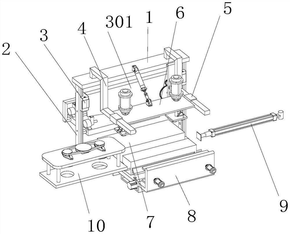
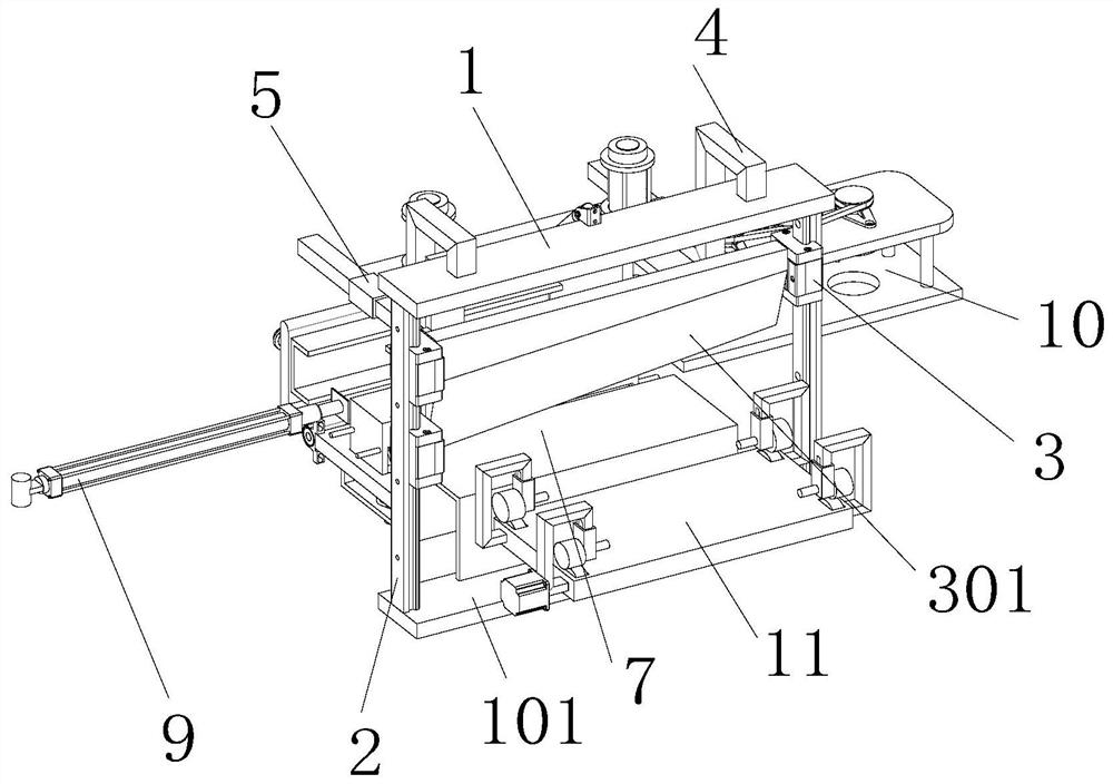
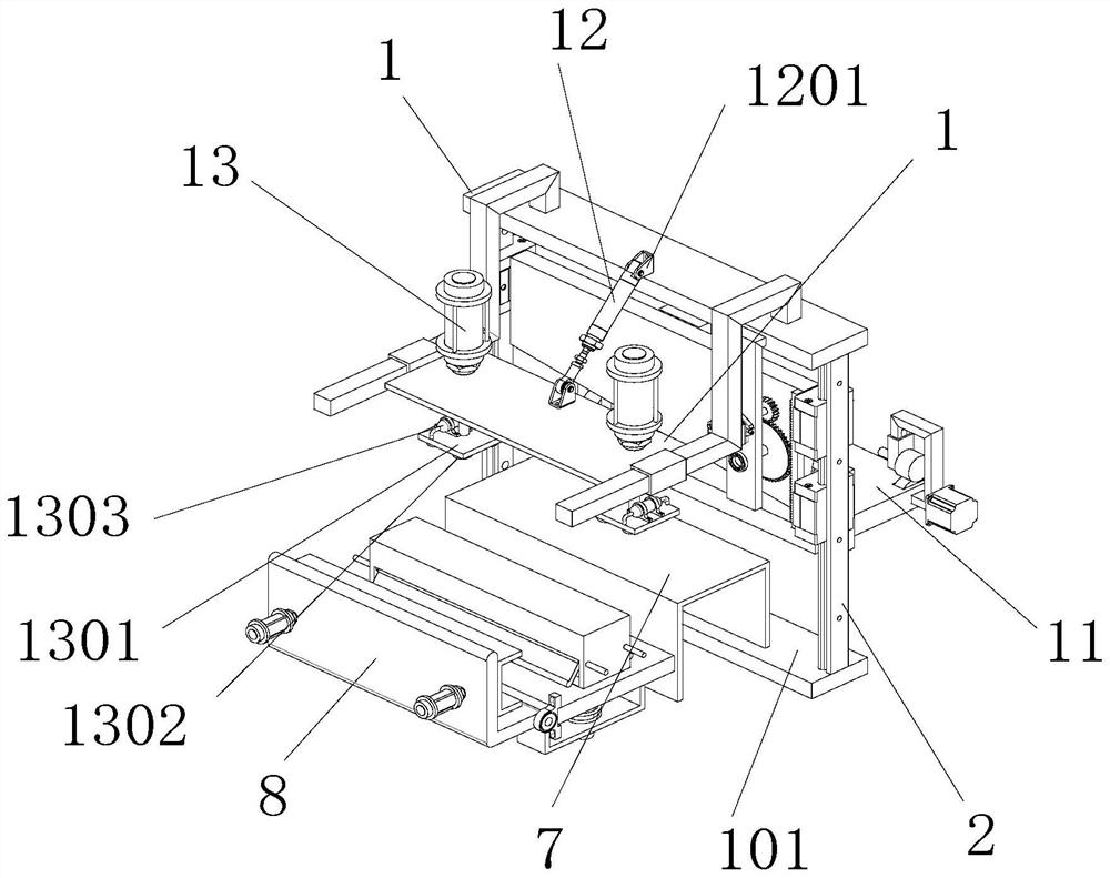
The invention discloses a laser cutting mechanism, and belongs to the field of laser processing. The laser cutting mechanism comprises a top end plate, a bottom end plate is arranged below the top end plate, two vertical guide rails are arranged between the top end plate and the bottom end plate, the vertical guide rails are sleeved with vertical sliding blocks, and the vertical sliding blocks are in sliding connection with the vertical guide rails; one vertical guide rail is provided with two vertical sliding blocks, the number of the vertical sliding blocks is three, the middles of the vertical sliding blocks are fixedly provided with cutting knives, the widths of the two ends of the cutting knives are different, the longer ends of the vertical sliding blocks are fixedly connected with the side walls of two cutting knives; and one side of one vertical guide rail is provided with a feeding assembly, and a stamping assembly is arranged on the other side of the vertical guide rail, a cutting assembly is arranged on one side of the stamping assembly, a discharging air cylinder is arranged on the other side of the stamping assembly, and a square sheet plate for pushing is arranged at the output end of the discharging air cylinder. The cutting knives can slide along the vertical guide rails along with the vertical sliding blocks.

Description

technical field [0001] The invention relates to the field of laser processing, in particular to a laser cutting mechanism. Background technique [0002] With the development of industrial technology, modern sheet metal processing technology has become more and more perfect. In the past, sheet metal needs to be cut and bent during processing, but plasma or plasma is required to unload in the middle of sheet metal. Laser cutting, in the past industrial level, most cases use plasma cutting, the accuracy of laser cutting is relatively high, but the process cost of laser cutting is also high; [0003] The area and weight of the sheet metal are relatively large, and the loading and unloading of the sheet metal material is laborious, and the accuracy of manual positioning of the sheet metal is not high enough, and it is necessary to replace multiple stations during the processing of the sheet metal. The station is more troublesome and wastes a lot of manpower. Contents of the in...

Claims


Application Information

Patent Timeline
IPC IPC(8): B23K26/38B23K26/70B23P23/04
CPCB23K26/0093B23K26/38B23K26/702
Inventor 张仁虎
Owner 张仁虎
Learn More