
Raw material stirring device for 3D printing

A technology of 3D printing and stirring device, applied in the field of 3D printing, can solve the problems of lower quality of finished products, low thermal conductivity of expansion coefficient, agglomeration, etc., to meet the needs of use, improve the quality of finished products, and have the effect of simple structure

Inactive Publication Date: 2021-08-10
WUHU INST OF TECH
View PDF0 Cites 0 Cited by
  • Summary
  • Abstract
  • Description
  • Claims
  • Application Information

AI Technical Summary

Problems solved by technology

[0002] Ceramic 3D printing has the characteristics of layer-by-layer printing and molding. Compared with traditional ceramic manufacturing processes, the biggest advantages are high production accuracy, short production cycle, personalized production, diversity of ceramic materials and relatively low production costs. Ceramic materials It has the characteristics of high temperature resistance, wear resistance and corrosion resistance, and has high strength, low expansion coefficient and good thermal conductivity. It has more potential and advantages than plastic and metal materials at high temperature. The existing treatment method is to add chemical Additives to enhance its toughness. In the prior art, the mixing of chemical additives and ceramic materials is carried out through ordinary stirring devices. When mixing, the ceramic raw materials are easy to form agglomerates, resulting in uneven mixing with chemical additives, and ceramic materials Raw materials are easily attached to the inner wall of the mixing tank during mixing, requiring manual frequent shutdown and cleaning, which seriously affects the efficiency of mixing and stirring, resulting in a decrease in the quality of the finished product, which cannot meet the needs of use

Method used


Image

  • Raw material stirring device for 3D printing
  • Raw material stirring device for 3D printing
  • Raw material stirring device for 3D printing

Examples


Embodiment Construction

[0016] The present invention will be described in further detail below in conjunction with the accompanying drawings and specific embodiments:

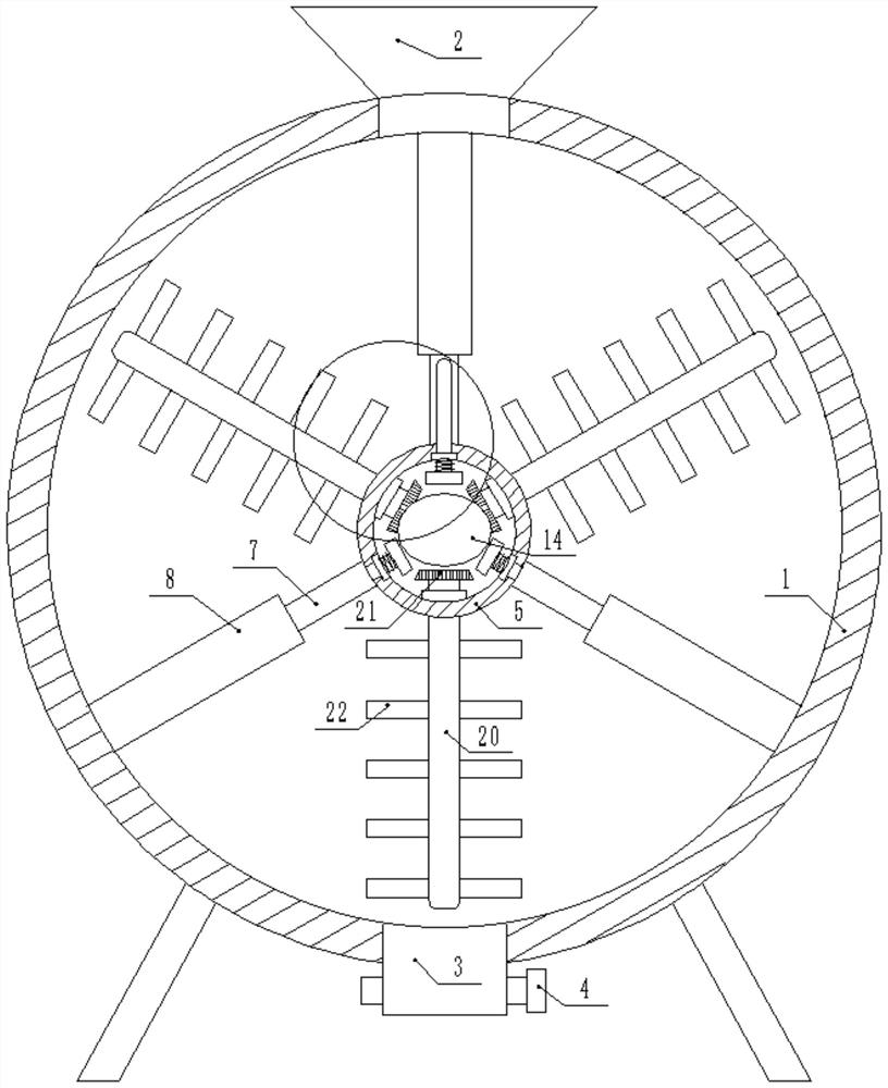
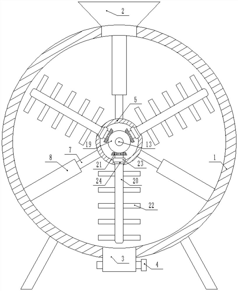
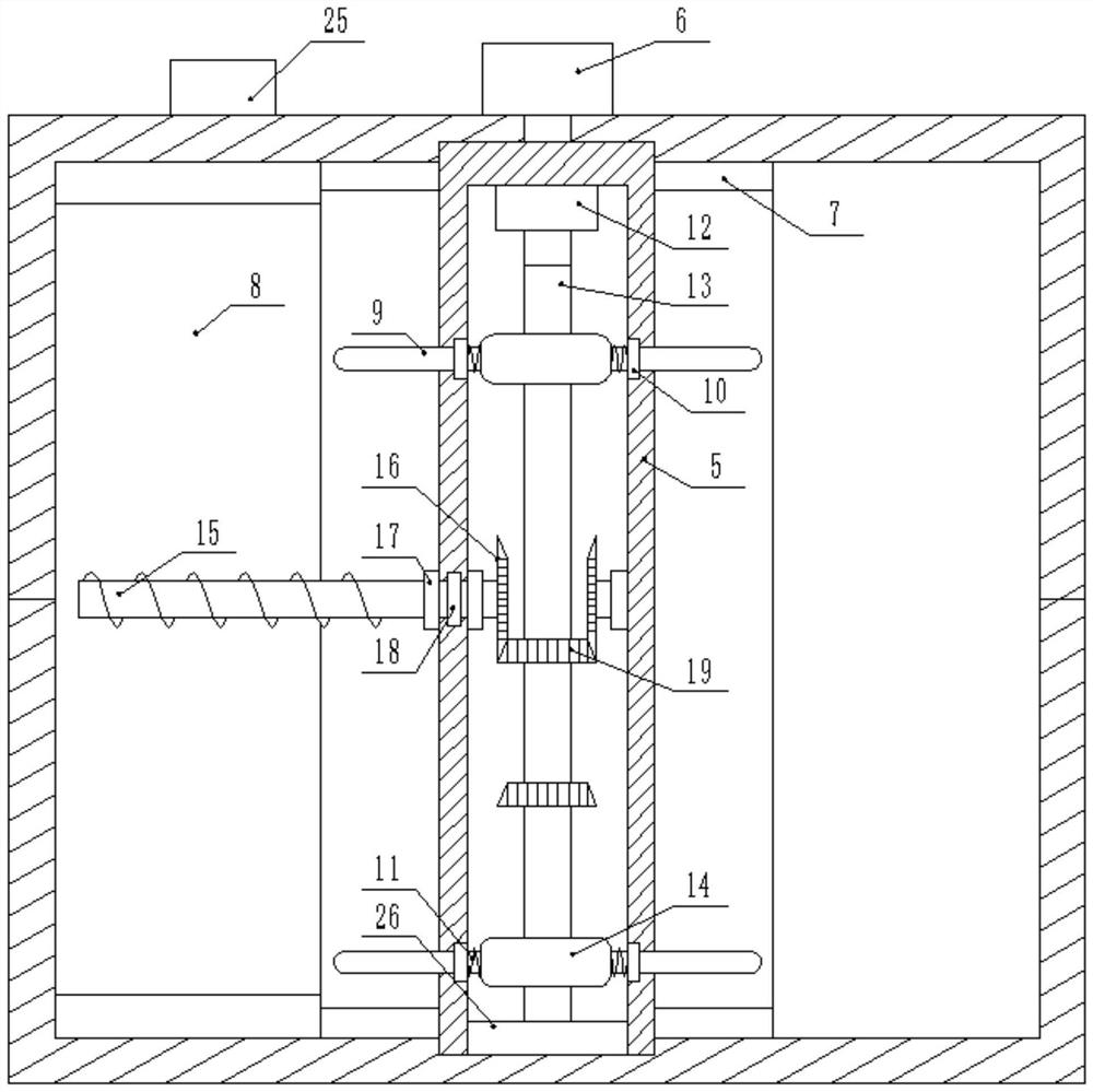
[0017] like figure 1 , figure 2 , image 3 , Figure 4 , Figure 5 As shown, a raw material stirring device for 3D printing includes a stirring barrel 1, the stirring barrel 1 is composed of a fixed connection between two semicircular barrels, and a plurality of legs are symmetrically and fixedly connected on the bottom surface of the stirring barrel 1, The top surface of the mixing bucket 1 is fixedly connected with a feeding funnel 2 , the bottom surface of the mixing bucket 1 is fixedly connected with a discharge pipe 3 , and a valve 4 is fixedly connected to the side wall of the discharge pipe 3 . A barrel body 5 is embedded in the mixing barrel 1 for rotation, and a deceleration motor 6 is fixedly connected to the side wall of the mixing barrel 1. The output end of the deceleration motor 6 penetrates into the mixing barrel 1...


PUM


Abstract

The invention discloses a raw material stirring device for 3D printing. The raw material stirring device for 3D printing comprises a stirring barrel, a motor is fixedly connected to the inner side wall of a barrel body, the output end of the motor is fixedly connected with a first rotating shaft, the first rotating shaft is fixedly sleeved with two rotating blocks, the side walls of the rotating blocks are attached to the surface of a T-shaped sliding rod, the side wall of the stirring barrel is fixedly connected with a PLC with a model of CPM1A-10CDR-A-V1, the PLC is electrically connected with a speed reduction motor and the motor, the other end of the first rotating shaft is fixedly connected with a sealing piece through glue, the surface of the sealing piece is attached to the inner wall of the barrel body, the model of the speed reduction motor is BWY27-23-7.5, the T-shaped sliding rod is made of alloy steel materials, and an inclined rod and an arc-shaped plate are connected in a welded mode. By means of the raw material stirring device for 3D printing, a chemical additive and ceramic raw materials can be fully stirred and mixed, the quality of finished products is improved, the chemical additive and the ceramic raw materials can be secondarily stirred, and therefore the quality of the finished products is indirectly improved, and use requirements are met.

Description

technical field [0001] The invention relates to the technical field of 3D printing, in particular to a high-efficiency raw material stirring device for 3D printing. Background technique [0002] Ceramic 3D printing has the characteristics of layer-by-layer printing. Compared with the traditional ceramic manufacturing process, the biggest advantage is that the production precision is high, the production cycle is short, the personalized production can be realized, the diversity of ceramic materials and the relatively low production cost. It has the characteristics of high temperature resistance, wear resistance and corrosion resistance, and has high strength, low expansion coefficient and good thermal conductivity. It has more potential and advantages than plastic and metal materials under high temperature. The existing treatment method is to add chemical Additives to enhance its toughness In the prior art, when chemical additives are mixed with ceramic materials, they are al...

Claims


Application Information

Patent Timeline
Patent Type & Authority Applications(China)
IPC IPC(8): B28B1/00B33Y30/00
CPCB28B1/001B33Y30/00
Inventor 徐光晨许佳潘友勇
Owner WUHU INST OF TECH
Learn More