Liquefied petroleum gas (LPG) buffer release tank and control system

A control system and buffer tank technology, applied in the direction of fixed-capacity gas storage tanks, container discharge methods, non-pressure vessels, etc., can solve problems such as splashing, incomplete vaporization, damage to ships and crews, etc., to avoid excessive backlog, Effects of improving safety and strengthening safety

Pending Publication Date: 2021-08-10
CHINA MERCHANTS HEAVY IND SHENZHEN
View PDF0 Cites 3 Cited by
  • Summary
  • Abstract
  • Description
  • Claims
  • Application Information

AI Technical Summary

Problems solved by technology

[0003] (1) There is no buffer tank, the vaporization is not complete when released, and the residual LPG liquid is easily splashed out through the ventilating mast, which will cause damage to the ship and crew
[0004] (2) There is no HC (hydrocarbon) content detection and nitrogen blowing, so it is impossible to know the explosive mixture in the venting mast, and it is impossible to clear it
[0005] In order to overcome the shortcoming that the common release pipe only has a ventilation mast, a buffer release tank and a control system are provided between the release valve group and the ventilation mast

Method used


Image

  • Liquefied petroleum gas (LPG) buffer release tank and control system
  • Liquefied petroleum gas (LPG) buffer release tank and control system

Examples


Embodiment 1

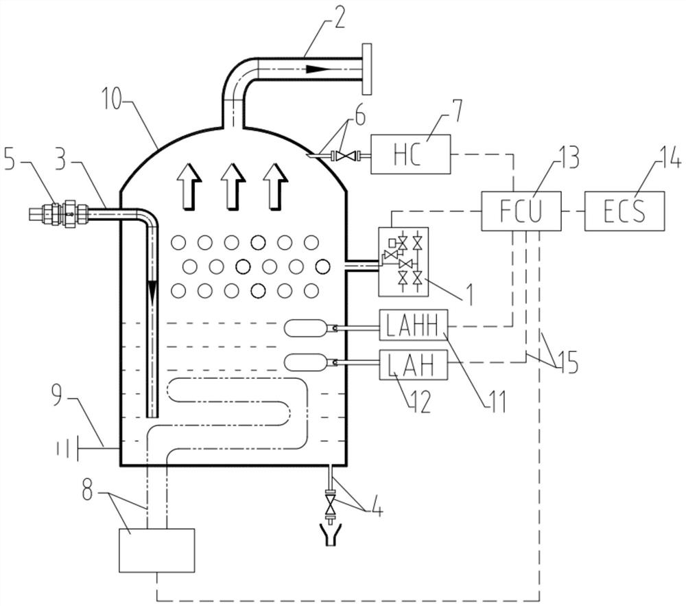
[0028] see figure 1 , an LPG buffer release tank and control system, divided into a buffer release tank part and an LPG control part, the buffer release tank part includes a release valve group 1 and a tank body 10, the release valve group 1 and the tank body 10 of the buffer release tank For communication, the highest part of the dome of the tank body 10 of the buffer release tank is fixedly installed with a discharge pipe 2, and the discharge port of the discharge pipe 2 is connected to the venting mast on the LPG ship, and one side of the tank body 10 is fixedly installed There is a nitrogen blow-off pipe 3, and a check valve 5 is fixedly installed on the nitrogen blow-off pipe 3;

[0029] The LPG control part includes a fuel control unit 13, a host control unit 14 and multiple sets of control signal lines 15, and the fuel control unit 13 and the host control unit 14 are respectively used for emergency response to the release valve group 1 and the control host of the LPG sh...

Embodiment 2

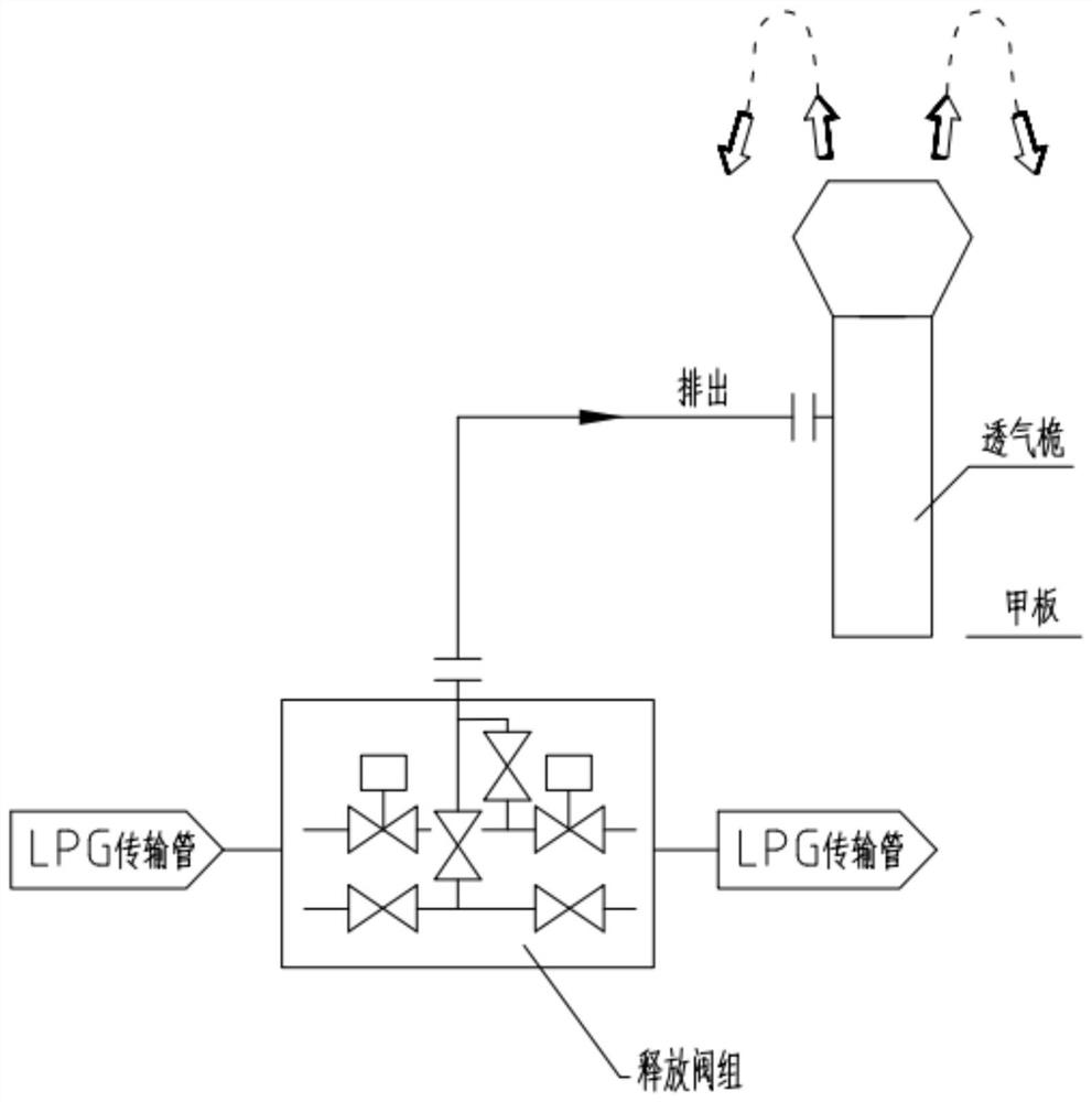
[0038] see figure 2, the common safety release line is directly released from the release valve group to the venting mast, which is used when the LPG power transmission pipe needs to be released urgently, resulting in incomplete vaporization during release, and it is easy to splash the residual LPG liquid through the venting mast, which will cause Injury to the ship and crew; and without HC (hydrocarbon) content detection and nitrogen blow-off, there is no way to know the explosive mixture in the vented mast, and there is no way to clean it up. Using the LPG buffer release tank and control system described in Embodiment 1, during emergency release, the release valve group 1 is opened, LPG enters the tank body 10 of the buffer tank, and the outlet of the tank body 10 of the buffer tank is at normal pressure After the LPG enters, it is vaporized under normal pressure, and part of the liquid drops to the bottom of the tank body 10 without enough time to vaporize. After the LPG v...


PUM


Abstract

The invention discloses a liquefied petroleum gas (LPG) buffer release tank and a control system, and belongs to the technical field of ship LPG power pipeline safety control. The LPG buffer release tank is divided into a buffer release tank part and an LPG control part, wherein the buffer release tank part comprises a release valve group and a tank body, the release valve group communicates with the tank body of the buffer release tank, a discharge pipe is fixedly mounted at the highest position of the top of the tank body of the buffer release tank, a discharge port of the discharge pipe communicates with a ventilation mast on an LPG ship, a nitrogen blow-off pipe is fixedly mounted on one side of the tank body, and a one-way valve is fixedly mounted on the nitrogen blow-off pipe. According to the LPG buffer release tank and the control system, the buffer tank is arranged, liquid left when LPG is not completely vaporized is collected, the released LPG is vaporized through the buffer release tank and then discharged to the ventilation mast to be discharged, the situation that the ship and sailors are hurt by liquid splashing is avoided, related equipment is displayed and remotely controlled through a fuel control unit, and multifunctional remote automatic control of the buffer tank is realized.

Description

technical field [0001] The invention belongs to the technical field of marine LPG power pipeline safety control, and specifically relates to an LPG buffer release tank and a control system. Background technique [0002] On LPG (liquefied petroleum gas) ships, the common safety release line is directly released from the release valve group to the venting mast for use when the LPG (liquefied petroleum gas) power transmission pipe needs to be released urgently, but in the prior art At present, this common design has the following problems and disadvantages: [0003] (1) There is no buffer tank, the vaporization is not complete during release, and the residual LPG liquid is easily splashed out through the vent mast, which will cause damage to the ship and crew. [0004] (2) Without HC (hydrocarbon) content detection and nitrogen blow-off, it is impossible to know the explosive mixture in the venting mast, and it is also impossible to clear it. [0005] In order to overcome the...

Claims


Application Information

Patent Timeline
Patent Type & Authority Applications(China)
IPC IPC(8): F17C3/00F17C13/12F17C13/02F17C13/04B63B25/12
CPCB63B25/12F17C3/00F17C13/021F17C13/04F17C13/12F17C2250/03F17C2270/0105
Inventor 王杨志孙瑞赵立玉张家茂张宝辉梁家日杨威
Owner CHINA MERCHANTS HEAVY IND SHENZHEN
Why Eureka
Try Eureka