
Distributed measurement method for motor rotor parameters of multiplexing rotary transformer

A technology of resolver and motor rotor, applied in electromagnetic measurement device, motor generator test, electromagnetic/magnetic position measurement, etc., can solve problems such as poor reliability, large centrifugal force, immaturity, etc., to improve system stability and reliability , The system is simple and accurate to grasp the effect

Inactive Publication Date: 2021-08-10
NAVAL UNIV OF ENG PLA
View PDF4 Cites 1 Cited by
  • Summary
  • Abstract
  • Description
  • Claims
  • Application Information

AI Technical Summary

Problems solved by technology

At the same time, with the increase of power density and speed, the difficulty of manufacturing large-capacity high-speed permanent magnet generators has increased significantly
Due to the high rotational speed and large centrifugal force, it is an important research topic to monitor the compressive stress between the permanent magnet and the rotor during manufacturing and operation. In the prior art, the measurement is generally achieved by installing a piezoresistive sensor. Components, the current high-speed rotor permanent magnet and the rotor compression stress measurement technology reliability is poor and immature

Method used


Image

  • Distributed measurement method for motor rotor parameters of multiplexing rotary transformer
  • Distributed measurement method for motor rotor parameters of multiplexing rotary transformer
  • Distributed measurement method for motor rotor parameters of multiplexing rotary transformer

Examples


Embodiment Construction

[0022] The present invention will be further described in detail below in conjunction with the accompanying drawings and specific embodiments.

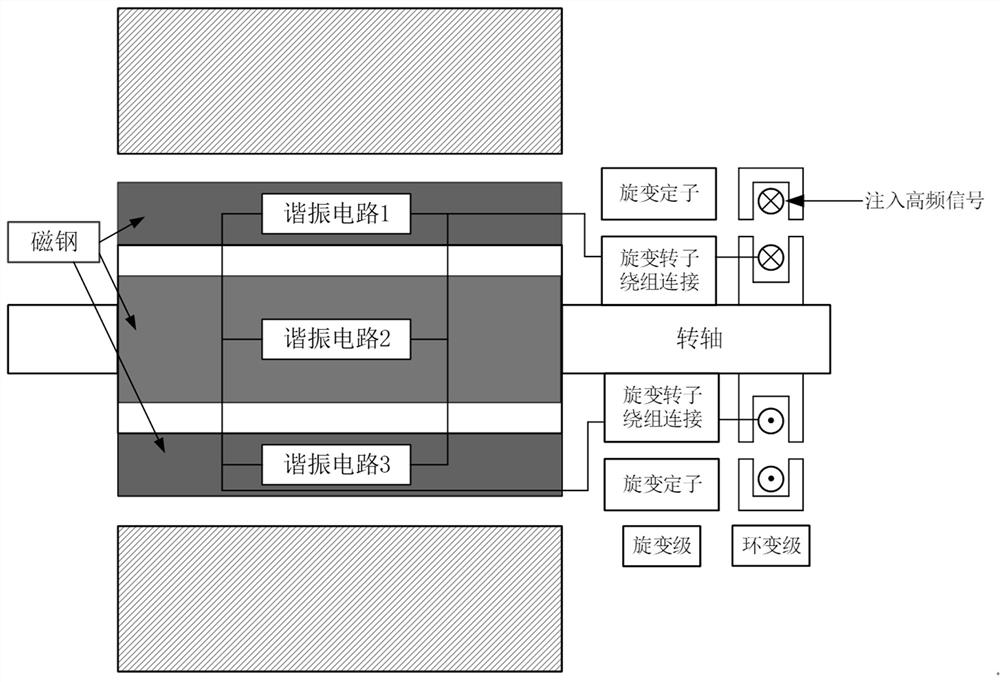
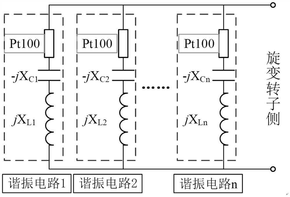
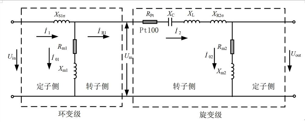
[0023] The invention discloses a method for distributed measurement of motor rotor parameters with a multiplexing rotary transformer, which is provided with a signal generator, a rotary transformer, a sensitive element, a resonant circuit and a signal demodulation circuit, and the signal generator provides high The frequency excitation signal, the input signal in the ring-changing rotor induction ring-changing stator of the resolver, the resolver-level rotor of the resolver is connected with the ring-changing rotor, the sensitive element is arranged on the point to be measured of the motor rotor, and the sensitive element and The resonant circuit is connected in series, and the resonant circuit with sensitive elements connected in series is connected between the ring transformer rotor and the resolver rotor. The resonant circuit matche...


PUM


Abstract

The invention relates to the technical field of motor state sensing and monitoring, and discloses a distributed measurement method for motor rotor parameters of a multiplex rotary transformer. A signal generator provides a high-frequency excitation signal for an annular variable-level stator, an annular variable-level rotor senses an input signal in the annular variable-level stator, a rotary variable-level rotor is connected with the annular variable-level rotor, a sensitive element is arranged on a to-be-measured point of a motor rotor, the sensitive element is connected in series with the resonant circuit, the resonant circuit is connected in series between the ring transformer stage rotor and the rotary transformer stage rotor, and the resonant circuit is matched with the excitation frequency of a high-frequency excitation signal generated by the signal generator; and the signal demodulation circuit obtains motor rotor parameter information from an output signal of the rotary transformer stage stator. According to the distributed measurement method for the motor rotor parameters of the multiplex rotary transformer, the rotor position measurement function of the rotary transformer is reserved, a traditional complex contact type feed and information transmission system can be abandoned, and real-time acquisition of the motor rotor parameters is achieved.

Description

technical field [0001] The invention relates to the technical field of motor state perception and monitoring, in particular to a method for distributed measurement of motor rotor parameters with a multiplexing resolver. Background technique [0002] The rotor temperature information of the motor is an important physical quantity that reflects the operating state of the motor. Especially for permanent magnet motors, the temperature of the permanent magnets in the rotor is of great significance to the reliable operation and reasonable control of the motor. When the temperature of the permanent magnet increases, its magnetic properties will decline to a certain extent, resulting in a decrease in the torque output capability and efficiency of the motor. If the temperature of the permanent magnet is too high, irreversible partial demagnetization may occur, which will affect the performance of the motor. permanent damage. [0003] It is precisely because of the above reasons that...

Claims


Application Information

Patent Timeline
IPC IPC(8): G01B7/00G01K7/22G01L5/00G01R31/34H02K11/21H02K11/25
CPCG01B7/003G01K7/22G01L5/0028G01R31/346H02K11/21H02K11/25
Inventor 胡靖华王东林黄达李文印黄文
Owner NAVAL UNIV OF ENG PLA
Learn More