
Power transformation box with magnetic variation type heat dissipation and cooling function

A transformer box and magnetic transformer technology, which is applied in the field of transformer boxes, can solve the problems of high operating cost, low heat dissipation efficiency, and insufficient sealing of the box body, and achieve the effects of low operating cost, high heat dissipation efficiency, and improved practicability

Pending Publication Date: 2021-08-10
熊怀双
View PDF0 Cites 3 Cited by
  • Summary
  • Abstract
  • Description
  • Claims
  • Application Information

AI Technical Summary

Problems solved by technology

[0003] During the use of the transformer box, a large amount of heat will be generated due to the operation of the equipment. If the heat cannot be dissipated in time, the transformer box will be burned and cause major economic losses. In the prior art, the heat dissipation of the transformer box is mainly in two forms , a type of heat dissipation without external power. This heat dissipation method mainly uses heat conduction through materials and opening vents to dissipate heat. Not only the heat dissipation efficiency is low and the effect is poor, but the opening of vents will make the box not sealed enough, and it is easy for dust and damp to enter. air, causing damage to the equipment in the box; the other is external power cooling, mainly including air cooling, water cooling, etc. Although the cooling efficiency and effect of this cooling method have been improved, the structure is complex, the operating cost is high, and additional cooling is required. Power drive not only consumes high energy, but also generates extra heat while driving, which is poor in practicability

Method used


Image

  • Power transformation box with magnetic variation type heat dissipation and cooling function
  • Power transformation box with magnetic variation type heat dissipation and cooling function
  • Power transformation box with magnetic variation type heat dissipation and cooling function

Examples


Embodiment 1

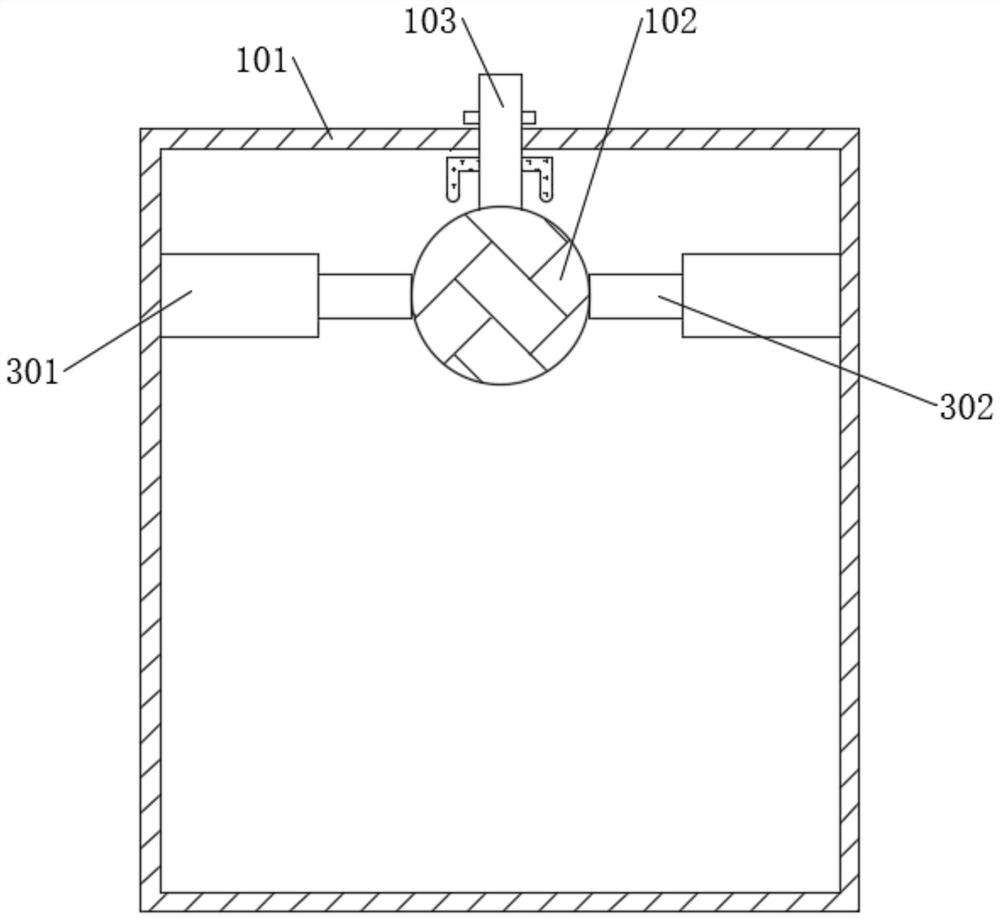
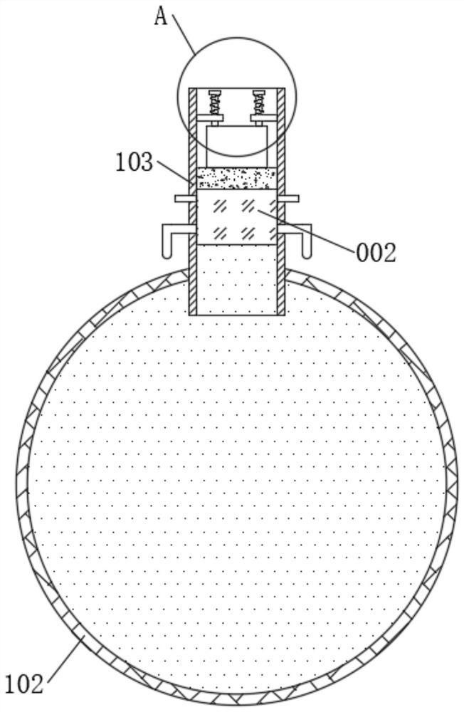
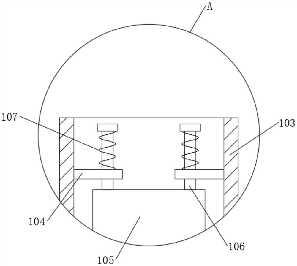
[0034] see Figure 1-7 , a transformer box with magnetic heat dissipation and cooling function, including a box body 101, an elastic balloon 102 is arranged inside, the top end of the elastic balloon 102 is connected with a ventilation tube 103, and the ventilation tube 103 runs through the top outer wall of the box body 101 Extending to the outer wall of the box body 101, and the vent tube 103 is sealed and fixedly connected with the top outer wall of the box body 101, the vent tube 103 can not only play a communication role, so that the elastic balloon 102 can communicate with the outside of the box body 101, but also Can play a fixed role, fix the elastic balloon 102 so that it will not fall, the ventilation pipe 103 is provided with a magnetic variable cooling body 002, and the magnetic variable cooling body 002 includes a heat-insulating storage box 201 that matches the ventilation pipe 103. The heat storage box 201 is sealed and fixedly connected with the inner wall of t...


PUM

PropertyMeasurementUnit
Curie pointaaaaaaaaaa

Abstract

The invention discloses a power transformation box with a magnetic variation type heat dissipation and cooling function, and belongs to the technical field of power transformation boxes. According to the transformation box, through arrangement of a magnetic variation cooling body, when the temperature in a box body is relatively high, a magnet block is heated and demagnetized, so that a magnetic variation refrigerant can be triggered to absorb heat and effectively cool the interior of the box body; a ventilation pipe can be conducted, air with heat in an elastic ball bag is exhausted out of the box body to cool the box body; through ingenious design of a damping driving and sucking assembly, after the air in the elastic ball bag is exhausted, the air with the low temperature can be sucked in from the outside again, the ventilation pipe is blocked again, and heat dissipation and cooling of the box body can be conducted repeatedly and continuously. Compared with the prior art, on the premise that sealing of the box body is not affected, heat dissipation is carried out by discharging and sucking air, the cooling function is achieved, the heat dissipation efficiency is high, the effect is good, additional power is not needed, the operation cost is low, and practicability is greatly improved.

Description

technical field [0001] The invention relates to the technical field of transformer boxes, and more specifically, relates to a transformer box with the function of magnetically changing heat dissipation and cooling. Background technique [0002] In the power system, the power plant converts natural primary energy into electric energy and transmits it to remote power users. In order to reduce the power loss and line impedance voltage drop on the transmission line, the voltage needs to be increased; in order to meet the safety requirements of power users It is necessary to reduce the voltage and distribute it to various users, which requires the ability to increase and decrease the voltage. The transformer box is the box in the place where the voltage and current of electric energy are transformed, concentrated and distributed in the power system. [0003] During the use of the transformer box, a large amount of heat will be generated due to the operation of the equipment. If t...

Claims


Application Information

Patent Timeline
IPC IPC(8): H02B1/56H02B1/46F25B21/00
CPCF25B21/00F25B2321/002H02B1/46H02B1/56Y02B30/00
Inventor 熊怀双
Owner 熊怀双
Learn More