
A kind of automatic welding machine and using method thereof

A technology of automatic welding machine and welding torch, which is applied in the direction of welding accessories, welding rod characteristics, and devices supporting electrode clamps, etc. It can solve the problems of automatic solder replenishment, single welding method, and unstable welding contact points, etc., and achieves wide applicability. Ease of use and simple structure

Active Publication Date: 2021-10-01
江苏金泰祥内外门业有限公司
View PDF0 Cites 0 Cited by
  • Summary
  • Abstract
  • Description
  • Claims
  • Application Information

AI Technical Summary

Problems solved by technology

[0003] However, the existing automatic electric welding machines still have many shortcomings in actual use, such as the inability to automatically replenish the solder, unstable welding contact points, and single welding methods.

Method used


Image

  • A kind of automatic welding machine and using method thereof
  • A kind of automatic welding machine and using method thereof
  • A kind of automatic welding machine and using method thereof

Examples


Embodiment Construction

[0043] The present invention will be specifically introduced below in conjunction with the accompanying drawings and specific embodiments.

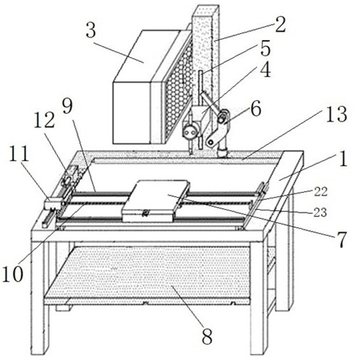
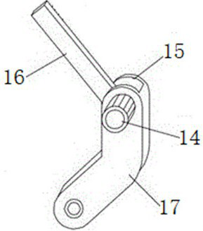
[0044] An automatic welding machine is composed of a welding station 1, a welding torch 4, a material supply box 3 and a torch pressing mechanism 6.

[0045] The middle part of the table top of the soldering station 1 is hollowed out, and the table top is ring-shaped; a pair of parallel first slide rails 9 are arranged horizontally and horizontally in the ring of the table top, and the two ends of the first slide rails are respectively (vertically) fixedly connected to the slide plate 22, the slide plate 22 slides along the second slide rail 23 arranged horizontally and longitudinally, and the second slide rail 23 is fixedly connected with the table top (or the ring side of the table top). The platen 7 is placed on the first slide rail 9 through the slideway on the bottom surface, and slides horizontally along the first slide rail 9; the ...


PUM


Abstract

An automatic welding machine and its use method, including a welding torch, a column arranged on the top side of the table, and a gun pressure mechanism; the spring is arranged in the sliding chamber of the column, the top end is fixed to the slider, the bottom end presses the first pressure sensor, and the side of the column There is a longitudinal chute with a transparent sliding cavity; a first motor for driving the first turntable at the end of the welding torch is installed inside, and the first turntable is fixedly connected with the slider through the chute; the welding head is arranged at the other end of the torch body, and the welding The first chuck in the head is driven by the second motor in the gun body; the gun pressing mechanism is set on the top of the support column through the rotating shaft, and the rotating shaft is driven by the third motor; the gun pressing arm presses the gun body, and the feeding arm lifts the gun body; the control The device drives the first motor to rotate the gun body according to the feedback from the first pressure sensor, and drives the second motor to link the first chuck; the third motor is driven by the control device. Through the feedback of the first and second pressure sensors, different forces at different stages are used as signals to realize the forward and reverse rotation of the rotating shaft, the rise and fall of the gun body, material supply, solder clamping and discarding, and welding automation.

Description

technical field [0001] The invention relates to an automatic welding machine, in particular to an automatic welding machine and a using method thereof. Background technique [0002] The automatic electric welding machine uses the high-temperature arc generated when the positive and negative poles are short-circuited instantaneously to melt the solder on the electric solder and the material to be welded, so that the objects to be contacted are combined. Using the principle of inductance, the inductance will change when it is turned on and off. A huge voltage change is generated, and the high-voltage arc generated when the positive and negative poles are short-circuited instantaneously is used to melt the solder on the electric solder, so that they can achieve the purpose of atomic bonding. [0003] However, the existing automatic electric welding machines still have many shortcomings in actual use, such as the inability to automatically replenish the solder, unstable welding ...

Claims


Application Information

Patent Timeline
Patent Type & Authority Patents(China)
IPC IPC(8): B23K9/28B23K9/32
CPCB23K9/287B23K9/32
Inventor 李苏州
Owner 江苏金泰祥内外门业有限公司
Learn More