
A self-positioning assembly system and method for rapid assembly of aircraft

An assembly system and self-positioning technology, which is applied to aircraft parts, transportation and packaging, workpiece clamping devices, etc., can solve the problems of weak rigidity of aircraft parts, idle forming frame resources, and complicated coordination relations, and achieve saving assembly space and site , improve assembly efficiency, and improve the effect of repeated utilization

Active Publication Date: 2021-10-01
CHENGDU AIRCRAFT INDUSTRY GROUP
View PDF9 Cites 0 Cited by
  • Summary
  • Abstract
  • Description
  • Claims
  • Application Information

AI Technical Summary

Problems solved by technology

Due to the weak rigidity, large quantity and complex coordination relationship of aircraft parts, aircraft assembly is different from general mechanical product assembly. It is necessary to use special assembly frames to shape and position aircraft parts. Due to the existence of a large number of assembly frames , leading to a long production preparation period of the aircraft, high manufacturing costs, and an unfriendly working environment for workers in the aircraft assembly process
[0003] A large number of truss-type welded frames are used in traditional aircraft assembly tooling, and the positioner and the frame are fixedly connected. The assembly of a type of aircraft product often requires hundreds of sets of assembly frames, and the assembly frames are only for one type of aircraft. For other Types of models that cannot be reused
Cause a lot of idle and waste of jig resources
The assembly method of the traditional aircraft fuselage structure is to shape and position more than 90% of the aircraft fuselage parts through the fuselage assembly jig. Traditional assembly jigs usually have specificity, low reuse rate and complex structure; therefore, in the field of aircraft assembly, it is urgent to design a positioning device that is easy to use, fast to install, accurate and easy to operate
[0004] In addition, aircraft assembly generally uses aircraft assembly jigs to realize aircraft assembly, and jigs take up a lot of space. Jigs are special process equipment in traditional aircraft assembly and are an important part of assembly tooling. They are closely related to aircraft structure. Therefore, the traditional assembly frame is generally difficult to adapt to the assembly of different types of aircraft
Whether the structural design of the assembly jig is reasonable and correct not only has a direct impact on the manufacturing workload, cycle length, cost, and assembly conditions of the assembly jig itself, but also determines whether the docking and matching dimensions of each workpiece are consistent, which affects the aircraft assembly. Interchange coordination, manufacturing quality and schedule have a great impact, affecting the entire aircraft manufacturing cycle

Method used


Image

  • A self-positioning assembly system and method for rapid assembly of aircraft
  • A self-positioning assembly system and method for rapid assembly of aircraft
  • A self-positioning assembly system and method for rapid assembly of aircraft

Examples


Embodiment 1

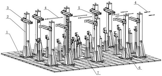
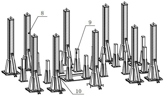
[0086] see Figure 1-3 , a self-positioning assembly system for aircraft rapid assembly of the present invention, including a mounting platform 1, a skeleton assembly 2, a hole locator assembly 3, a strut locator assembly 4, an intersection hole locator 5, a pallet assembly 6, Special positioning component 7 for the top support.

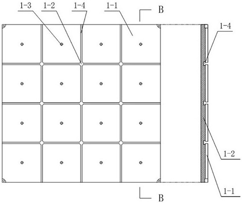
[0087] The installation platform 1 includes an installation substrate 1-1 and an installation base 1-2. A plurality of installation substrates 1-1 are arranged in an array and connected to the installation base 1-1. The installation base is placed on the foundation. The block mounting substrate 1-1 and the mounting base 1-2 form a T-shaped notch 1-4 that intersects vertically and horizontally, and the T-shaped notch 1-4 is used to connect the mounting plate of the skeleton assembly.

[0088] Due to the large mass of the installation base plate 1-1, in the actual installation process, lifting equipment such as a gantry crane is required for auxiliary...

Embodiment 2

[0111] see Figure 10-2 with Figure 10-3 , in this embodiment, the positioning pin assembly 21 is a "Z-shaped" positioning pin assembly, including a latch 32, a channel bushing 33, a cylindrical pin 34, and a bushing 35, and the channel bushing 33 has a shape of "Z". font" track groove, the channel bushing 33 is fixed on the slide rail support 20, the bushing 35 is fixed on the bottom plate 27, the lower part of the bolt 32 is connected with the bushing 35, the middle part of the bolt 32 is provided with a cylindrical pin 34, and the cylindrical Pin 34 is used for spacing, and latch 32 slides along " zigzag " track groove, and when sliding to track groove bottom, rotation locks. In the process of plugging and unplugging, the latch 32 slides out along the top of the "Z-shaped" track groove of the channel liner 33, effectively preventing the latch 32 from falling. Compared with the "spiral-shaped" locating pin assembly, the "Z-shaped" locating pin assembly in this embodiment ...

Embodiment 3

[0115] The fuselage structure mainly includes the main frame and the main beam of the fuselage. Therefore, the fuselage assembly frame is mainly for the positioning of the frame and beam structure. The traditional assembly method adopts tooling positioning for most of the fuselage main frame and fuselage main beam structure. Therefore, due to the compact structure of the fuselage, the tooling structure is abnormally composite, and there are many positioners. The traditional assembly tooling device or tooling system has a skeleton structure The lack of closure and many locators not only brings about the improvement of tooling manufacturing cycle and cost, but also greatly affects the efficiency of on-site assembly. Therefore, in order to improve the efficiency of aircraft assembly and reduce the assembly cycle and cost, the present invention proposes a An assembly method of a self-positioning assembly system for rapid assembly.

[0116] Such as Figure 16-1 The frame positioni...


PUM


Abstract

The invention discloses a self-positioning assembly system and method for rapid assembly of aircraft. The aircraft tooling positioning device specifically includes an installation platform, a skeleton assembly, a hole locator assembly, a strut locator assembly, and a supporting plate assembly; the advantages are: Skeleton components adopt the assembly method of scattered column groups, which saves the assembly space to the greatest extent. The aircraft structure self-positioning assembly concept is adopted to reduce the tooling structure. Workers can flexibly enter and exit the assembly space to perform workpiece positioning and assembly operations, and A new type of more efficient positioning assembly for hole locators, strut locators, and swivel supports is proposed. Through coarse adjustment of columns and fine adjustment of various locator components, self-positioning assembly and modularization of the aircraft are realized. Assembling improves the efficiency of aircraft assembly. The invention is applicable to the assembly of different models and improves the reutilization rate of tooling.

Description

technical field [0001] The invention relates to the technical field of aircraft assembly, in particular to a self-positioning assembly system and method for rapid assembly of aircraft. Background technique [0002] Aircraft assembly has strict process requirements. The assembly parts used with positioning requirements are referred to as positioning assembly devices or positioning tooling devices. relationship, improving aircraft production efficiency and reducing costs. Due to the weak rigidity, large quantity and complex coordination relationship of aircraft parts, aircraft assembly is different from general mechanical product assembly. It is necessary to use special assembly frames to shape and position aircraft parts. Due to the existence of a large number of assembly frames , leading to a long production preparation cycle of the aircraft, high manufacturing costs, and an unfriendly working environment for workers in the aircraft assembly process. [0003] A large numbe...

Claims


Application Information

Patent Timeline
Patent Type & Authority Patents(China)
IPC IPC(8): B23P19/00B25B11/02
CPCB23P19/00B25B11/02B23P2700/01B64F5/10B64F5/50
Inventor 隋少春饶华赵颖毕修文邓珍波李绍杰游诗茂王明
Owner CHENGDU AIRCRAFT INDUSTRY GROUP
Learn More