Installation method of coiled tubing defect stenciling system

A system installation and oil pipe technology, which is applied to printing devices, typewriters, printing, etc., can solve the problems that affect the safety of oil pipe operations and cannot be accurately positioned, and achieve the effect of facilitating re-inspection and repairing, ensuring operation safety, and preventing deviation

Active Publication Date: 2021-08-13
BC P INC CHINA NAT PETROLEUM CORP +1
View PDF6 Cites 1 Cited by
  • Summary
  • Abstract
  • Description
  • Claims
  • Application Information

AI Technical Summary

Problems solved by technology

However, for the collected defect magnetic flux leakage signal, it is still necessary to manually analyze the filtered waveform diagram to determine whether there is a defect and the approximate location of the defect. The location of the defect cannot be accurately located, which affects the safety of the oil pipeline operation.

Method used


Image

  • Installation method of coiled tubing defect stenciling system

Examples


Embodiment 1

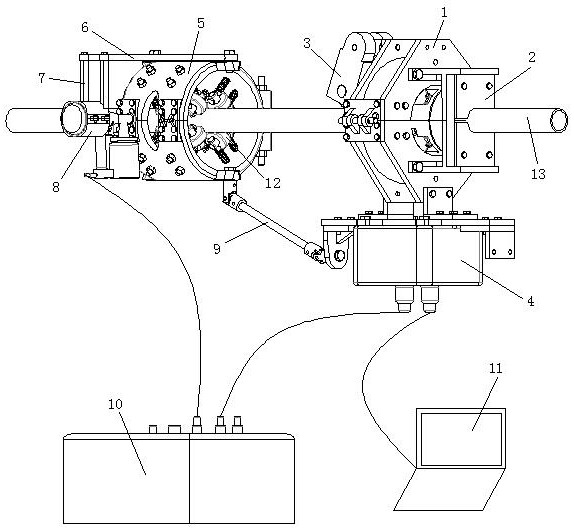
[0033] see figure 1 , a coiled tubing defect spray marking system installation method, comprising the following steps:

[0034] S1, install the coiled tubing 13 through the marking positioning device, and set the roller encoder 3 on the magnetic flux leakage detection unit 1 of the coiled tubing magnetic flux leakage detection device;

[0035] S2, then the marking positioning device is connected with the electric control box 10, the coiled tubing magnetic flux leakage detection device is connected with the signal processing box 4, and the signal processing box 4 is connected with the electric control box 10 and the computer 11 respectively;

[0036] S3. Finally, insert the debugged paint spray gun 8 into the spray gun ferrule 7, and align the nozzle of the paint spray gun 8 with the wall of the coiled tubing 13.

[0037] This embodiment is the most basic implementation mode, S1, install the coiled tubing 13 through the marking positioning device, set the roller encoder 3 on t...

Embodiment 2

[0039] seefigure 1 , a coiled tubing defect spray marking system installation method, comprising the following steps:

[0040] S1, install the coiled tubing 13 through the marking positioning device, and set the roller encoder 3 on the magnetic flux leakage detection unit 1 of the coiled tubing magnetic flux leakage detection device;

[0041] S2, then the marking positioning device is connected with the electric control box 10, the coiled tubing magnetic flux leakage detection device is connected with the signal processing box 4, and the signal processing box 4 is connected with the electric control box 10 and the computer 11 respectively;

[0042] S3. Finally, insert the debugged paint spray gun 8 into the spray gun ferrule 7, and align the nozzle of the paint spray gun 8 with the wall of the coiled tubing 13.

[0043] In the step S1, setting the coiled tubing 13 through the marking positioning device specifically refers to installing the coiled tubing 13 on the support base ...

Embodiment 3

[0046] see figure 1 , a coiled tubing defect spray marking system installation method, comprising the following steps:

[0047] S1, install the coiled tubing 13 through the marking positioning device, and set the roller encoder 3 on the magnetic flux leakage detection unit 1 of the coiled tubing magnetic flux leakage detection device;

[0048] S2, then the marking positioning device is connected with the electric control box 10, the coiled tubing magnetic flux leakage detection device is connected with the signal processing box 4, and the signal processing box 4 is connected with the electric control box 10 and the computer 11 respectively;

[0049] S3. Finally, insert the debugged paint spray gun 8 into the spray gun ferrule 7, and align the nozzle of the paint spray gun 8 with the wall of the coiled tubing 13.

[0050] In the step S1, setting the coiled tubing 13 through the marking positioning device specifically refers to installing the coiled tubing 13 on the support bas...


PUM


Abstract

The invention discloses an installation method of a coiled tubing defect stenciling system, and belongs to the technical field of oil pipe detection. The method is characterized by comprising the following steps that S1, coiled tubing is arranged in a stenciling and positioning device in a penetrating manner, and a roller encoder is arranged on a magnetic flux leakage detection unit of a coiled tubing magnetic flux leakage detection device; S2, the stenciling and positioning device is connected to an electric control box, the coiled tubing magnetic flux leakage detection device is connected to a signal processing box, and the signal processing box is connected to the electric control box and a computer; and S3, finally, a debugged paint spraying gun is embedded into a spraying gun clamping sleeve, and a nozzle of the paint spraying gun is aligned with the pipe wall of the coiled tubing. The whole installation process is convenient and fast, stable connection of the coiled tubing magnetic flux leakage detection device and the stenciling and positioning device can be achieved, accurate stenciling and positioning of defects are achieved, the operation safety of the coiled tubing is guaranteed, and the operation cost can be reduced.

Description

technical field [0001] The invention relates to the technical field of oil pipe detection, in particular to an installation method of a coiled oil pipe defect spraying system. Background technique [0002] With the rapid development of unconventional oil and gas, unconventional operations are increasing year by year. Unconventional oil and gas mainly include tight sandstone oil and gas reservoirs, tight carbonate rock oil and gas reservoirs, shale oil and gas reservoirs and coalbed methane. Coiled tubing operations, which have a series of advantages of short operation period, can be lifted and lowered under pressure, safety and high efficiency, cost reduction and reservoir damage reduction, are more and more favored by various oil companies. Coiled tubing has been widely used in sand washing, well washing, salvage, gas lift drainage, drilling and grinding bridge plugs, perforation, logging of highly deviated wells and horizontal wells, acidizing and fracturing of oil and wa...

Claims


Application Information

Patent Timeline
Patent Type & Authority Applications(China)
IPC IPC(8): B41J2/01B41J3/407B41J29/393B41J29/46
CPCB41J2/01B41J3/4073B41J29/393B41J29/46
Inventor 王哲张健万夫卢秀德刘炯黄敏向刚任能彭鑫蔡洵
Owner BC P INC CHINA NAT PETROLEUM CORP
Why Eureka
Try Eureka