Environment-friendly automobile exhaust treatment system and treatment method

A technology of automobile exhaust and treatment system, which is applied in the direction of exhaust device, air quality improvement, noise reduction device, etc. It can solve the problem that the three-way catalytic converter does not have the catalytic ability, prolongs the working time of the three-way catalytic converter, and the second carrier is blocked And other issues

Active Publication Date: 2021-08-13
宁波明讯实业有限公司 +1
View PDF6 Cites 0 Cited by
  • Summary
  • Abstract
  • Description
  • Claims
  • Application Information

AI Technical Summary

Problems solved by technology

[0004] The three-way catalytic converter does not have the ability to catalyze at room temperature, and its catalyst must be heated to a certain temperature to have the ability to oxidize or reduce. However, the temperature in the exhaust pipe of the existing car cannot reach the work of the three-way catalytic converter when it is just started. The best solution is to preheat the three-way catalytic converter. However, there is no preheating equipment in the existing three-way catalytic converter, which prolongs the working time of the three-way catalytic converter. At the same time, the three-way catalytic converter The second carrier of the catalytic converter will form water during operation. After condensation, the water will easily combine with the suspended solid particles in the exhaust gas and adhere to the second carrier. If things go on like this, it will easily block the second carrier.

Method used


Image

  • Environment-friendly automobile exhaust treatment system and treatment method
  • Environment-friendly automobile exhaust treatment system and treatment method
  • Environment-friendly automobile exhaust treatment system and treatment method

Examples


Embodiment 1

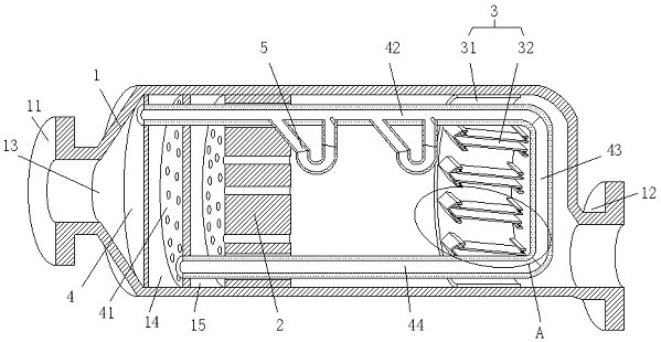
[0041] see Figure 1-2, an environment-friendly automobile exhaust treatment system, comprising a cylinder 1, one end of the cylinder 1 is communicated with an intake pipe 11, the other end of the cylinder 1 is communicated with an outlet pipe 12, and the cylinder 1 is installed with The honeycomb-shaped first carrier 2 is used to catalyze the reduction of automobile exhaust. The first carrier 2 is mainly coated with metals such as platinum and rhodium as a catalyst to catalyze the reduction of nitrogen oxides into nitrogen and oxygen. The cylinder 1 A second carrier 3 is also installed inside for catalytic oxidation of automobile exhaust, the first carrier 2 is close to the intake pipe 11, and the second carrier 3 is close to the outlet pipe 12;

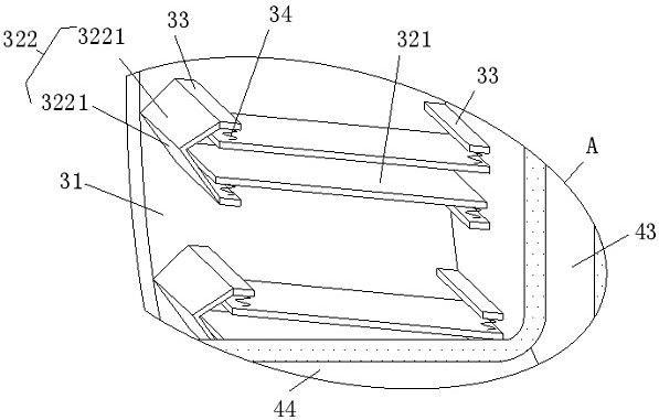
[0042] The second carrier 3 includes a support cylinder 31 installed in the cylinder body 1, and multiple groups of oxidation units 32 are installed in the support cylinder 31, and the oxidation unit 32 includes two oxygen oxidation...

Embodiment 2

[0047] This embodiment is an explanation made on the basis of Embodiment 1, and on the basis of the accompanying drawings of Embodiment 1, please refer to the accompanying drawings again. Figure 3-4 .

[0048] Specifically, the preheating assembly includes a sealing plate 4 and a deflector plate 41 installed in the cylinder body 1, the sealing plate 4 is located between the intake pipe 11 and the first carrier 2, and is used to block The inner space of cylinder body 1 prevents the exhaust gas from being directly transmitted from the inlet pipe 11 to the outlet pipe 12, the first diversion space 13 is formed between the sealing plate 4 and the inlet pipe 11, and the diversion plate 41 is located in the Between the first carrier 2 and the sealing plate 4, a second flow guiding space 14 is formed between the guide plate 41 and the sealing plate 4, and between the guide plate 41 and the first carrier 2 forming a third diversion space 15;

[0049] The sealing plate 4 is also com...

Embodiment 3

[0061] This embodiment is an improvement made on the basis of Embodiment 1, see Figure 1-4 , the oxidation substrate 321 is arranged obliquely; wherein, the oxidation substrate 321 slopes obliquely downward from an end far away from the air outlet pipe 12 to an end close to the air outlet pipe 12 .

[0062] The inclined setting of the oxidation substrate 321 helps the solid particles on the substrate to shake off and slide to the lower right of the cylinder body 1, and it should be noted that the air outlet pipe 12 is also installed at the lower right end of the cylinder body 1, so that these particles can be discharged from the outlet. Trachea 12 cleared out.

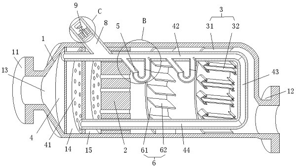
[0063] Further, a flow guide assembly 6 is installed in the cylinder body 1; the flow guide assembly 6 includes a flow guide cylinder 61 installed in the cylinder body 1, and a plurality of flow guide substrates installed in the flow guide cylinder 61 62 , there is a gap between adjacent flow-guiding substrates 62 , ...


PUM


Abstract

The invention relates to the technical field of tail gas treatment, and discloses an environment-friendly automobile exhaust treatment system and a treatment method. The environment-friendly automobile exhaust treatment system comprises a cylinder, one end of the cylinder communicates with a gas inlet pipe, the other end of the cylinder communicates with a gas outlet pipe, and a honeycomb-shaped first carrier is installed in the cylinder; and the first carrier is used for catalytic reduction of automobile exhaust, a second carrier is further installed in the cylinder and used for catalytic oxidation of the automobile exhaust, the first carrier is close to the gas inlet pipe, and the second carrier is close to the gas outlet pipe. According to the environment-friendly automobile exhaust treatment system, when the automobile exhaust enters the second carrier, an oxidation base plate in each oxidation unit in the second carrier vibrates under the influence of automobile exhaust flow, and the vibration easily shakes off solid particulate matter on the oxidation base plates, so that the situation that a large number of solid particulate matter is gathered on the oxidation base plates is avoided, and the catalytic oxidation of the second carrier on the automobile exhaust is facilitated.

Description

technical field [0001] The invention relates to the technical field of tail gas treatment, in particular to an environment-friendly automobile tail gas treatment system and a treatment method. Background technique [0002] Automobile exhaust pollution is environmental pollution caused by exhaust gas emitted by automobiles. The main pollutants in automobile exhaust are carbon monoxide, hydrocarbons, nitrogen oxides and solid particles suspended in automobile exhaust. The air is seriously polluted. [0003] In order to reduce the air pollution caused by automobile exhaust, in the prior art, people usually install a three-way catalytic converter on the exhaust pipe of the automobile to purify the exhaust gas of the automobile. The interior of the three-way catalytic converter mainly includes two honeycomb-shaped carriers , these two carriers can be ceramic or metal, the first carrier is mainly coated with metals such as platinum and rhodium as catalysts, which are used to cata...

Claims


Application Information

Patent Timeline
Patent Type & Authority Applications(China)
IPC IPC(8): F01N3/28F01N3/20F01N3/10F01N3/34F01N13/08
CPCF01N3/106F01N3/2006F01N3/2803F01N3/34F01N13/08Y02A50/20
Inventor 黄绍荣罗署
Owner 宁波明讯实业有限公司
Why Eureka
Try Eureka