Super high-rise tube well stand tube upside-down mounting construction method

A construction method, technology of inversion method, applied in the direction of pipes/pipe joints/fittings, pipe laying and maintenance, mechanical equipment, etc., can solve the problem of increasing the number of vertical and horizontal transportation of pipelines, the difficulty of vertical connection between upper and lower risers, and increasing Problems such as labor and materials can reduce the number of horizontal and vertical transportation, reduce maintenance costs in the later period, and eliminate poor welding quality.

Pending Publication Date: 2021-08-13
CHINA SHANXI SIJIAN GRP
View PDF11 Cites 3 Cited by
  • Summary
  • Abstract
  • Description
  • Claims
  • Application Information

AI Technical Summary

Problems solved by technology

[0003] However, while super-high-rise buildings bring convenience to people, they also bring great challenges to construction. For example, in a project with a total height of 245.8 meters, the tube well runs through from the third floor to the 46th floor. The maximum pipe diameter is φ377*9, and there are 8 pipes in total. The hoisting and construction of the riser in the pipe well is difficult. The traditional process is to connect and install pipes one by one from the bottom to the top. Pipes must be placed on each floor to transport the pipes horizontally to the pipe well, increasing the number of pipes The number of vertical and horizontal transportation; during the installation process, the hoisting point is constantly moved along with the floor, which increases labor and materials; the construction speed is slow and other shortcomings; , It is difficult to achieve vertical connection between the upper and lower risers

Method used


Image

  • Super high-rise tube well stand tube upside-down mounting construction method
  • Super high-rise tube well stand tube upside-down mounting construction method

Examples


Embodiment Construction

[0020] Take a construction project as an example:

[0021] According to the design and distribution of the riser of the project tube well, the construction of the riser is divided into three construction sections: the low area, the middle area and the high area according to the number of building floors. The 33rd floor to the 46th floor of the construction section in the middle area is considered as the construction section in the high area.

[0022] All tube well risers are transported and placed at the corresponding tube wells on the first floor. The construction sequence is the "inverted method" from the high area to the low area. The hoisting equipment mainly includes tools such as electric hoists, manual hoists, and wire ropes.

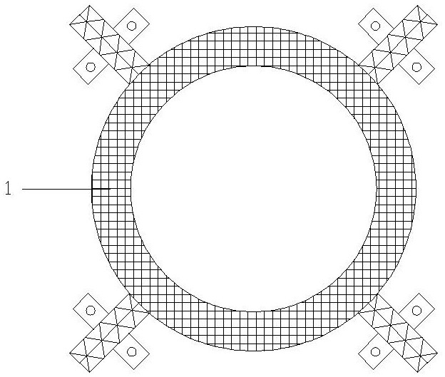
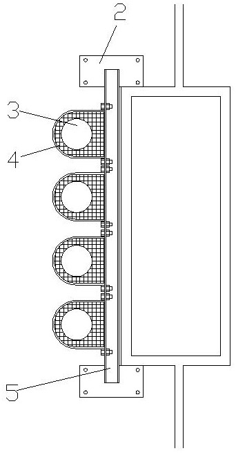
[0023] Such as figure 1 , 2 As shown, a super-high-rise tube well standpipe "flip-chip method" installation and construction method, the specific steps are as follows.

[0024] S100~Based on the number of building floors, it is divided into th...


PUM


Abstract

The invention belongs to the technical field of building high-rise tube well mounting construction, and particularly relates to a super high-rise tube well stand tube upside-down mounting construction method. The super high-rise tube well stand tube upside-down mounting construction method comprises the following steps that S100, a building is divided into three construction sections including a low area, a middle area and a high area according to the number of floors; S200, a tube well stand tube is transported to the position of the corresponding tube well of the first layer, a main hoist is mounted on the highest layer of the low area, an auxiliary hoist is mounted on a top plate of the tube well of the first layer, and construction is carried out in sequence from the high area to the low area; S300, at the position of the first-layer tube well, a main hoist located at the top plate of the highest-layer tube well in the low area is used for lifting and hoisting the first section of pipeline; S400, the auxiliary hoist at the top plate of the first-layer tube well is used for lifting a vertical second section of pipeline; S500, positioning of the first section of pipeline and the second section of pipeline is adjusted, overall lifting is carried out, and the steps are sequentially repeated for welding and lifting till the whole vertical tube is connected; S600, pipeline connection of other vertical tubes in the high area is carried out; and S700, the step S200 and the step S600 are repeated, and the vertical tubes of the middle area construction section and the low area construction section are sequentially constructed.

Description

technical field [0001] The invention belongs to the technical field of installation and construction of high-rise pipe wells in buildings, and in particular relates to a method for installation and construction of super-high-rise pipe well standpipes "inverted". Background technique [0002] In recent decades, with the rapid development of the economy and the advancement of science and technology, super high-rise buildings have also shown a phenomenon of rapid development. Super high-rise skyscrapers have sprung up everywhere, and have become new landmarks in many cities. In today's land shortage and dense population, super high-rise buildings have many advantages in urban construction. Super high-rise buildings occupy a small area, improve land utilization, expand urban open space, benefit urban greening, and improve sanitation. At the same time, due to the compact urban land use, facilities such as roads and pipelines can be concentrated, and municipal investment costs c...

Claims


Application Information

Patent Timeline
Patent Type & Authority Applications(China)
IPC IPC(8): F16L1/024F16L1/06
CPCF16L1/0246F16L1/06
Inventor 赵羽斌卫芷王文涌刘勇庆穆锦峰秦宏磊
Owner CHINA SHANXI SIJIAN GRP
Why Eureka
Try Eureka