Online repairing structure of double-shaft humidifying stirrer of dust remover

A technology for repairing structures and mixers, applied to mixer accessories, mixers with rotating agitation devices, mixers, etc., can solve the problems of poor humidification effect of dry ash, waste of spare parts costs, waste of humidifiers, etc., to save spare parts, save Maintenance time and improvement of maintenance efficiency

Pending Publication Date: 2021-08-17
HEBEI IRON AND STEEL
View PDF6 Cites 0 Cited by
  • Summary
  • Abstract
  • Description
  • Claims
  • Application Information

AI Technical Summary

Problems solved by technology

The current treatment method is that if any break occurs during use, the normal use of the equipment is generally restored by replacing the new humidifier as a whole, but often the rest of the humidifier system is relatively good, and the overall replacement of the humidifier causes a certain degree of waste
[0005] (3) After the cutter head fixed on the upper part of the blade in the box was worn out, it was not replaced in time, which caused the blade to be evenly ground down by about 30mm-40mm along the height direction, resulting in poor ash transportation, poor humidification effect of dry ash, and serious dust emission , while the thickness of the blade is still qualified, and the welding between the lower part of the blade and the surface of the shaft is still very firm
The treatment method is generally to cut off the worn blades, weld new blades, and then install and fix the cutter head, which is time-consuming and laborious, resulting in a certain degree of waste of spare parts cost
[0006] In view of the above-mentioned difficult-to-handle failures in the existing dual-axis humidifiers, it is very necessary to improve the existing dual-axis humidifiers to achieve the purpose of repairing them quickly and conveniently

Method used


Image

  • Online repairing structure of double-shaft humidifying stirrer of dust remover
  • Online repairing structure of double-shaft humidifying stirrer of dust remover
  • Online repairing structure of double-shaft humidifying stirrer of dust remover

Examples


Embodiment Construction

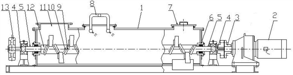
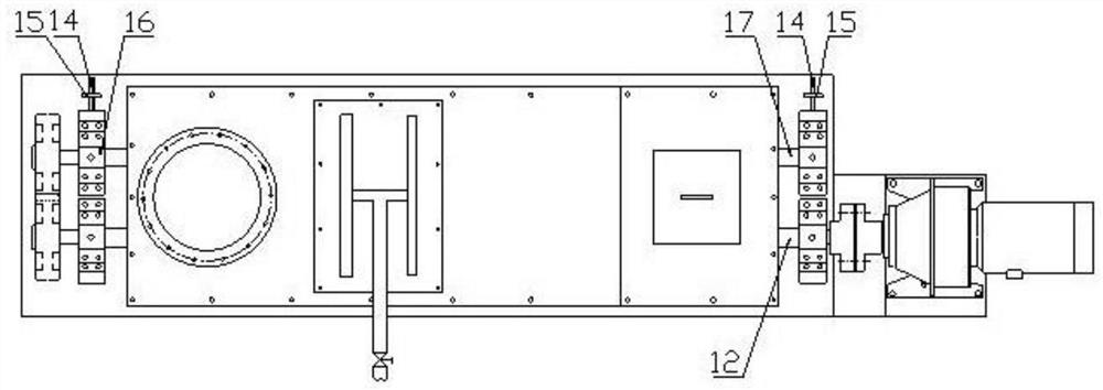
[0023] The present invention consists of a box body 1, a motor and a reducer 2, a shaft coupling 3, a driving shaft 12, a driven shaft 17, a bearing seat 16, a bearing 28, a blade 9, a cutter head 10, a pair of meshing spur gears 13, a seal Baffle plate 6 is formed.

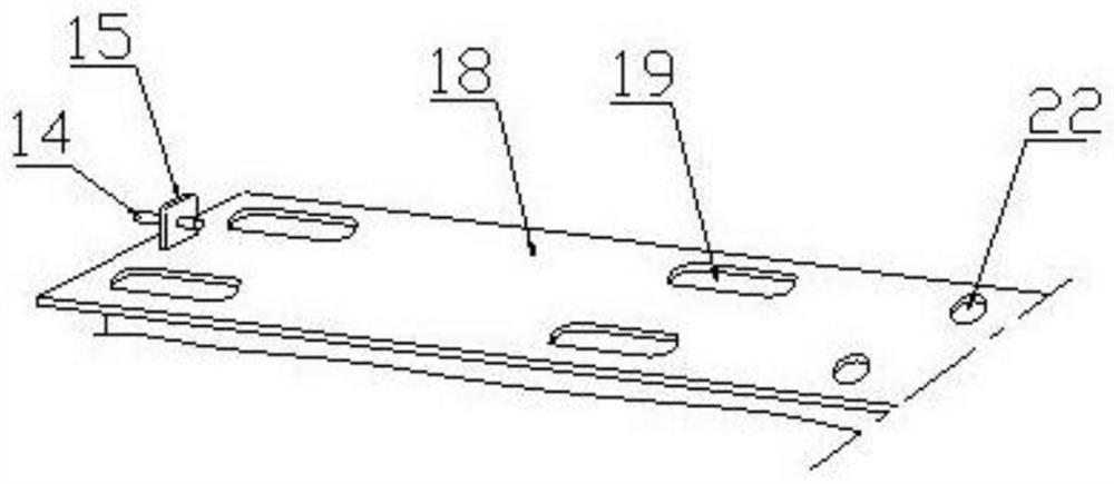
[0024] As shown in the figure, the driving shaft 12 and the driven shaft 17 are installed in parallel in the casing 1 of the humidifier. There is a sealing baffle 6 at the end of the casing 1, and two bearing seats 16 are respectively arranged at both ends of the casing 1. The bearing seats 16 is a split four-screw bearing seat, wherein bearing 28 is installed. Motor and speed reducer 2, shaft coupling 3 are connected with the front end of drive shaft 12, and the rear end of drive shaft 12 and driven shaft 17 is equipped with spur gear 13 respectively, and the spur gear 13 of drive shaft 12 and driven shaft 17 rear end Mesh. The lower part of the blade 9 is welded on the driving shaft 12 and the driven shaft 17...


PUM


Abstract

The utility model discloses an online repairing structure of a double-shaft humidifying stirrer of a dust remover, belongs to the technical field of dust remover stirrer equipment, and is used for repairing the double-shaft humidifying stirrer. According to the technical scheme, an adjusting top plate is vertically welded to the upper surface of a box body bottom plate on the outer side of the rear end of a driven shaft, a lead screw hole is formed in the adjusting top plate, and an adjusting lead screw is screwed in the lead screw hole; when the easily-broken part of the driving shaft is broken, a dummy shaft for repairing is arranged, one end of the driving shaft is matched with the shaft device and the bearing, the end face of the other end is of a sleeve structure, and the maintenance end of the driving shaft is embedded in the end face sleeve of the dummy shaft and fixedly connected; after the blades are abraded, maintenance blades are additionally arranged and are arc-shaped manganese steel plates, the lower ends of the maintenance blades are welded to the upper ends of the abraded blades, and the tool bits are installed on the maintenance blades through fixing bolts. The online repairing structure is simple in structure and convenient to use, the problems of blade clamping, driving shaft breaking and blade abrasion caused by gear abrasion or gear tooth abutting and offside can be rapidly solved, the maintenance time is greatly saved, and the maintenance cost is reduced.

Description

technical field [0001] The invention relates to a double-shaft humidifying mixer for a dust removal system of a dust collector, and belongs to the technical field of dust collector mixer equipment. Background technique [0002] At present, the double-shaft humidifying mixer is widely used in the dry dust removal and ash removal system with small density and fine particles in the iron and steel complex, and the blast furnace purification dust collection and ash removal system. The twin-shaft mixer has the advantages of compact structure, small footprint, stable transmission, low noise, uniform mixing, and reliable operation. , transported by car to a centralized mixing site for recycling, effectively avoiding the phenomenon of dust in the process of loading and transporting dust, and meeting the requirements of environmental protection for outbound transportation. However, in use, it is found that the current twin-shaft mixer is prone to the following three difficult-to-hand...

Claims


Application Information

Patent Timeline
IPC IPC(8): B01F15/00B01F7/04
CPCB01F27/70B01F35/00
Inventor 李凤涛高玲玲袁平刚王刚白雪皎周海峰
Owner HEBEI IRON AND STEEL
Why Eureka
Try Eureka