Response solving method and device of rotor system

A rotor and system establishment technology, applied in the field of rotor system response solution, can solve problems such as inaccurate matrix modal solution, matrix inversion and solution eigenvalue numerical error, and complex structure parameter matrix, etc., to improve calculation efficiency and calculation The effect of precision

Pending Publication Date: 2021-08-17
AERO ENGINE ACAD OF CHINA
View PDF0 Cites 2 Cited by
  • Summary
  • Abstract
  • Description
  • Claims
  • Application Information

AI Technical Summary

Problems solved by technology

[0003] When performing modal analysis on an unconstrained freely supported rotor system, due to the large number of nodes and degrees of freedom in the finite element method, the matrix of each structural parameter is complicated, and leads to numerical errors in matrix inversion and solution of eigenvalues, which will eventually lead to matrix Problems such as inaccurate modal solution

Method used


Image

  • Response solving method and device of rotor system
  • Response solving method and device of rotor system
  • Response solving method and device of rotor system

Examples


Embodiment 1

[0072] At present, the analysis methods of dynamic characteristics of flexible rotor system mainly include transfer matrix method and finite element method. In the transfer matrix method, the order of the transfer matrix does not increase with the degree of freedom of the rotor system, so the programming is simple and the operation speed is fast. Therefore, for a long time, the transfer matrix method has dominated the research on the dynamics of flexible rotor systems, but when this method is used to solve the dynamics problems of high-speed large-scale rotor systems, numerical instability may occur. Moreover, the transfer matrix method is not easy to solve the nonlinear problem of the rotor system.

[0073] The finite element method for analyzing rotor dynamics was initially only used to study the bending vibration of the rotor. With the gradual deepening of the research, the finite element model of the rotor was also continuously improved, and the model gradually included th...

Embodiment 2

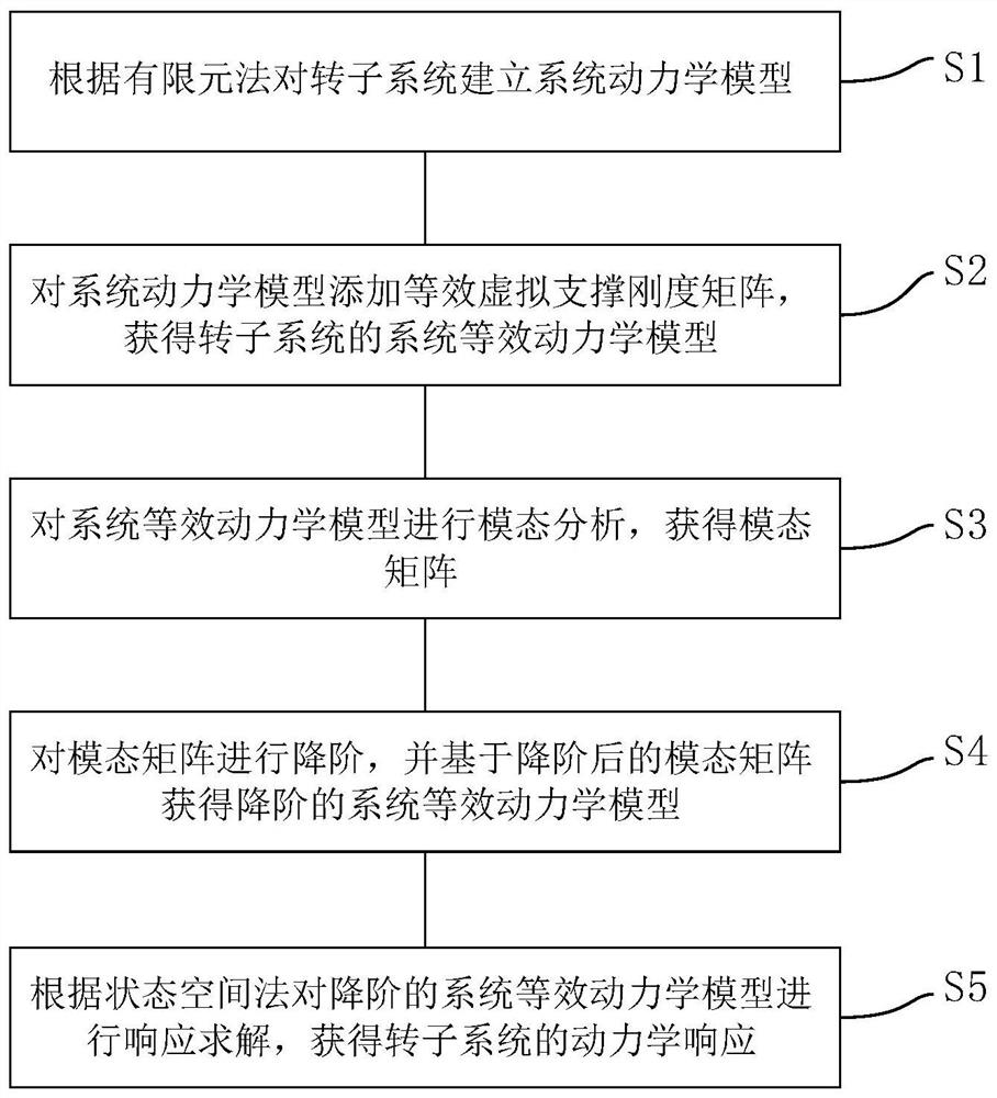
[0147] refer to Figure 6 , an embodiment of the present invention also provides a response solution device for a rotor system, including:

[0148] A dynamic model building module, used to establish a system dynamic model for the rotor system according to the finite element method;

[0149] The equivalent dynamic model acquisition module is used to add an equivalent virtual support stiffness matrix to the system dynamic model to obtain the system equivalent dynamic model of the rotor system;

[0150] The modal analysis module is used to perform modal analysis on the equivalent dynamic model of the system to obtain the modal matrix;

[0151] The equivalent dynamic model reduction module is used to reduce the order of the modal matrix, and obtain the reduced-order equivalent dynamic model of the system based on the reduced modal matrix;

[0152] The response solving module is used to solve the response of the reduced-order system equivalent dynamic model according to the state s...


PUM


Abstract

The invention provides a response solving method and device for a rotor system. The method comprises the following steps: establishing a system dynamic model for the rotor system according to a finite element method; adding an equivalent virtual support stiffness matrix to the system dynamic model to obtain a system equivalent dynamic model of the rotor system; performing modal analysis on the system equivalent dynamic model to obtain a modal matrix; performing order reduction on the modal matrix, and obtaining an order-reduced system equivalent dynamic model based on the modal matrix after order reduction; and performing response solving on the reduced-order system equivalent dynamic model according to a state space method to obtain the dynamic response of the rotor system. According to the method, the equivalent virtual support is added in the system dynamic model, so that stable modal separation of the algorithm is ensured, and the order reduction is performed on the modal matrix, so that the order-reduced system equivalent dynamic model is obtained, and the calculation efficiency and the calculation precision of rotor system response are improved. The device is used for implementing the method.

Description

technical field [0001] The invention relates to the technical field of rotor systems, in particular to a method and device for solving the response of a rotor system. Background technique [0002] In order to improve power density and energy conversion efficiency, the operating speed of the rotor is often unavoidably higher than the bending critical speed. When the rotor speed increases, it needs to exceed the rigidity and low-order bending critical speed of the system. At this time, due to the unbalanced mass of the rotor, severe resonance usually occurs, so the analysis of the dynamic characteristics of the rotor system is very important. [0003] When performing modal analysis on an unconstrained freely supported rotor system, due to the large number of nodes and degrees of freedom in the finite element method, the matrix of each structural parameter is complicated, and leads to numerical errors in matrix inversion and solution of eigenvalues, which will eventually lead t...

Claims


Application Information

Patent Timeline
Patent Type & Authority Applications(China)
IPC IPC(8): G06F30/23G06F119/14
CPCG06F30/23G06F2119/14
Inventor 张生光张学宁胡文颖陈霞
Owner AERO ENGINE ACAD OF CHINA
Why Eureka
Try Eureka