
Femoral stem prosthesis electrolytic machining cathode and femoral stem prosthesis electrolytic machining device

A technology for processing devices and femoral stems, which is applied in the direction of electric processing equipment, electrochemical processing equipment, and accessory devices, can solve the problems of low processing accuracy, high processing cost, and low efficiency, and achieve good surface quality of finished products and reduce processing costs , Improve the effect of machining accuracy

Pending Publication Date: 2021-08-20
GUANGDONG UNIV OF TECH
View PDF6 Cites 2 Cited by
  • Summary
  • Abstract
  • Description
  • Claims
  • Application Information

AI Technical Summary

Problems solved by technology

[0005] The purpose of the present invention is to overcome the technical problems of low processing accuracy, low efficiency and high processing cost in the existing manufacturing method for processing femoral stem prosthesis

Method used


Image

  • Femoral stem prosthesis electrolytic machining cathode and femoral stem prosthesis electrolytic machining device
  • Femoral stem prosthesis electrolytic machining cathode and femoral stem prosthesis electrolytic machining device
  • Femoral stem prosthesis electrolytic machining cathode and femoral stem prosthesis electrolytic machining device

Examples


Embodiment 1

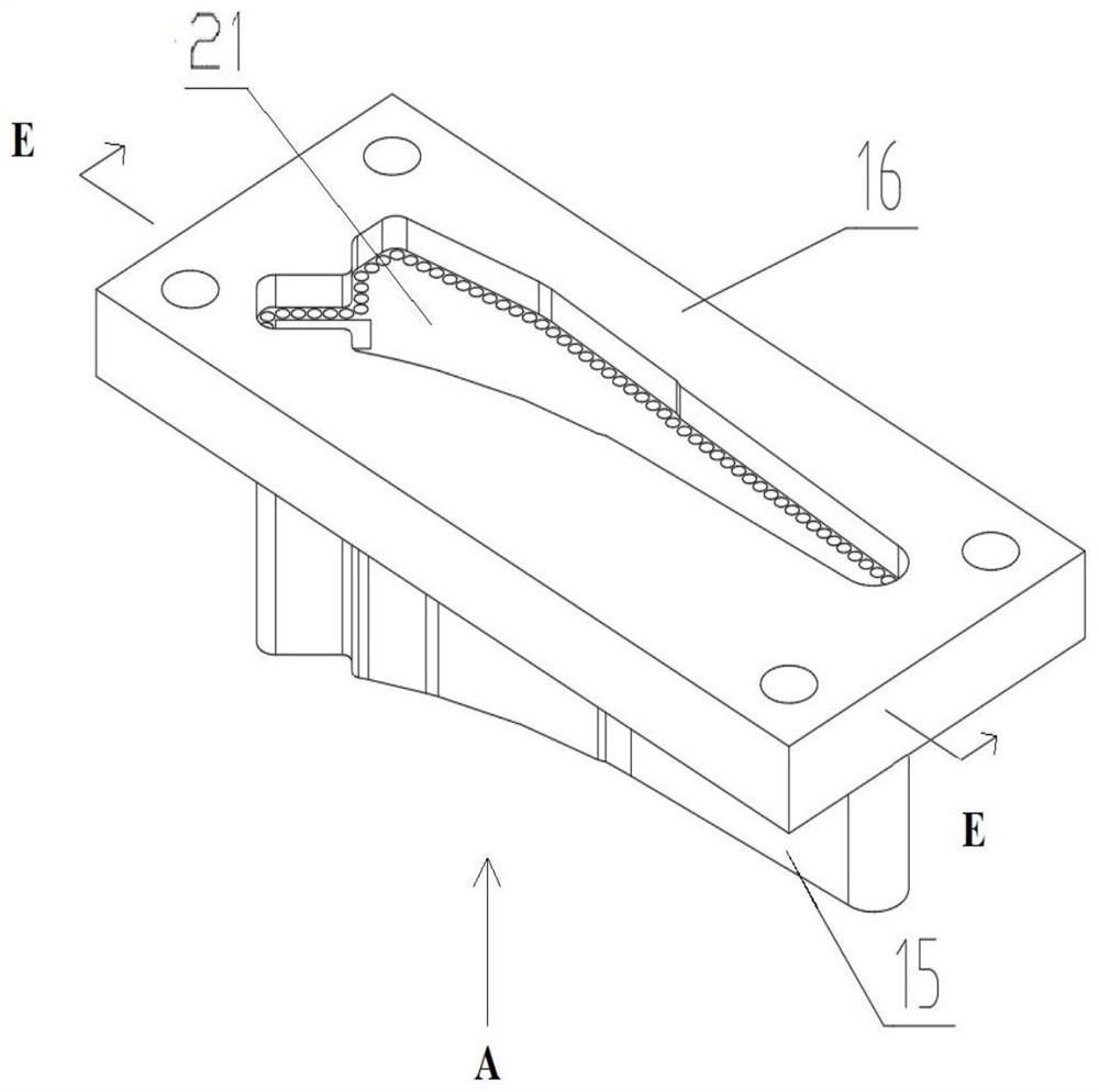
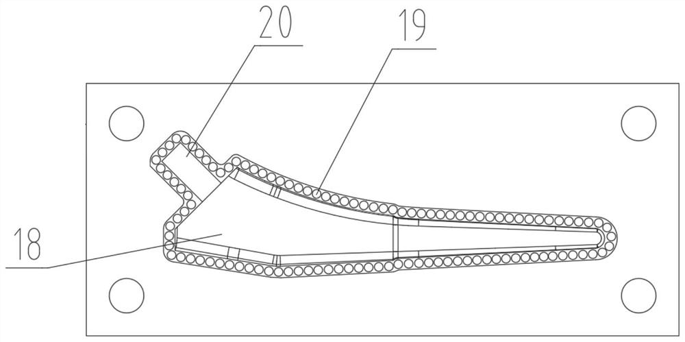
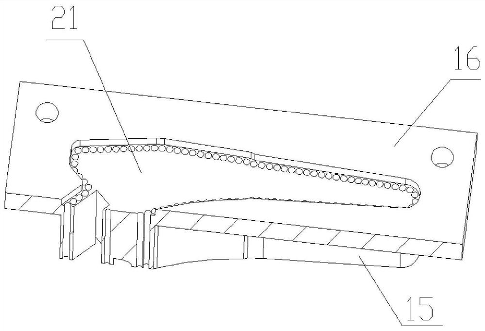
[0035] Such as Figure 1 to Figure 4 As shown, a femoral stem prosthesis electrolytically processed cathode includes a cathode base plate 16 and a cathode forming body 15 located on one side of the cathode base plate 16. The end face of the cathode forming body 15 away from the cathode base plate 16 is the processed end face, and the profile of the processed end face Adapt to the outline of the cross-section of the femoral stem prosthesis at its symmetry plane, the edge position of the processed end face is provided with the outline through hole 19 that runs through the cathode molding main body 15 and the cathode base plate 16, and the outline of the outline through hole 19 on the processed end surface is consistent with The profile of the section of the femoral stem prosthesis at its symmetry plane is consistent, and an inner cavity 18 adjacent to the profile through hole 19 is also provided on the processed end surface, and the inner profile of the inner cavity 18 is symmetr...

Embodiment 2

[0042] This embodiment is similar to Embodiment 1, except that, in this embodiment, the diameter of the contour through hole 19 is 2 mm. The structure and working principle of other parts of this embodiment are the same as those of Embodiment 1.

Embodiment 3

[0044] This embodiment is similar to Embodiment 1, except that, in this embodiment, the diameter of the contour through hole 19 is 4 mm. The structure and working principle of other parts of this embodiment are the same as those of Embodiment 1.


PUM


Abstract

The invention provides a femoral stem prosthesis electrolytic machining cathode comprising cathode bottom plates and cathode forming main bodies, the end face of the end, away from the corresponding cathode bottom plate, of each cathode forming main body is a machining end face, and contour through holes penetrating through the corresponding cathode forming main body and the corresponding cathode bottom plate are formed in the edge position of each machining end face. An inner mold cavity adjacent to the corresponding contour through holes is further formed in each machining end face, and a handle part through hole is formed in the position, used for forming a femoral stem prosthesis handle part, of each inner mold cavity. The invention further provides a femoral stem prosthesis electrolytic machining device comprising the femoral stem prosthesis electrolytic machining cathode. The technical problems that an existing manufacturing method for machining the femoral stem prosthesis is low in machining precision and efficiency and high in machining cost are solved. The femoral stem prosthesis electrolytic machining cathode can be applied to an electrolytic machining method to serve as the electrolytic cathode, the structure is simple, and cutting of the contour of the femoral stem prosthesis and electrolytic forming of a complex profile in electrolytic machining can be completed at a time.

Description

technical field [0001] The invention relates to the technical field of femoral stem prosthesis for medical implants, and more specifically, to a femoral stem prosthesis electrolytic machining cathode and a femoral stem prosthesis electrolytic machining device. Background technique [0002] The artificial hip joint prosthesis imitates the structure of the human hip joint. The stem of the femoral stem is inserted into the femoral medullary cavity, and the femoral flexion, extension and movement are realized by using the rotation joint formed by the head and the joint socket or the metal cup of the prosthesis. Necrosis of the femoral head, femoral neck fracture in advanced age, comminuted acetabular fracture, femoral head tumor and other diseases require artificial hip replacement to replace the necrotic hip joint to maintain joint function. The femoral stem prosthesis is a part with a complex profile. The materials used for this part include stainless steel, cobalt-chromium-mo...

Claims


Application Information

Patent Timeline
IPC IPC(8): B23H3/00B23H11/00
CPCB23H3/00B23H11/00
Inventor 陈晓磊胥中正张永俊于兆勤
Owner GUANGDONG UNIV OF TECH
Learn More