Auxiliary supporting and adjusting equipment for rotor shaft machining and use method thereof

A technology for auxiliary support and adjustment of equipment, applied in the direction of metal processing equipment, metal processing machinery parts, supports, etc., can solve the problems of easily hurting workers, inconvenience, and affecting the processing environment of the factory area, so as to save processing time and avoid cutting deviation. Effect

Inactive Publication Date: 2021-08-20
南通捷越机电有限公司
View PDF11 Cites 1 Cited by
  • Summary
  • Abstract
  • Description
  • Claims
  • Application Information

AI Technical Summary

Problems solved by technology

[0003] Existing rotor shafts will produce a large amount of cutting during cutting. Due to the lack of cutting collection devices in existing cutting devices, chips generally fly directly in the air. On the one hand, the flying chips are easy to hurt workers; It affects the processing environment of the factory area. At the same time, most of the existing rotor shafts are fixed by manually turning the bolts during cutting, which is very inconvenient. Therefore, an auxiliary support adjustment device for rotor shaft processing and its use method are needed to solve the above problems.

Method used


Image

  • Auxiliary supporting and adjusting equipment for rotor shaft machining and use method thereof
  • Auxiliary supporting and adjusting equipment for rotor shaft machining and use method thereof
  • Auxiliary supporting and adjusting equipment for rotor shaft machining and use method thereof

Examples


Embodiment Construction

[0029] In order to make the above objects, features and advantages of the present invention more comprehensible, specific implementations of the present invention will be described in detail below in conjunction with the accompanying drawings. In the following description, numerous specific details are set forth in order to provide a thorough understanding of the present invention. However, the present invention can be implemented in many other ways different from those described here, and those skilled in the art can make similar improvements without departing from the connotation of the present invention, so the present invention is not limited by the specific implementations disclosed below.

[0030] It should be noted that when an element is referred to as being “fixed” to another element, it can be directly on the other element or there can also be an intervening element. When an element is referred to as being "connected to" another element, it can be directly connected ...


PUM


Abstract

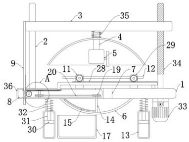
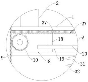
The invention discloses auxiliary supporting and adjusting equipment for rotor shaft machining, comprising a supporting plate. A sliding rod is fixedly connected to the supporting plate; a lifting plate is slidably connected to the sliding rod; a connecting column is fixedly connected to the lifting plate; a cutting machine is fixedly connected to the lower end of the connecting column; protective covers are arranged on the supporting plate and the connecting column; a cleaning mechanism used for removing scrap iron generated during cutting is arranged in the protective cover at the lower end; a moving mechanism used for moving the lifting plate is arranged at the right end of the supporting plate; a guide opening matched with a cutting machine is formed in the supporting plate; and a cavity is formed in the supporting plate. The invention further discloses a use method of the auxiliary supporting and adjusting equipment for rotor shaft machining, comprising steps of S1, S2 and S3. The equipment is reasonable in structure, a rotor shaft can be automatically fixed before cutting, and meanwhile, cuttings can be collected to avoid splashing of the cuttings.

Description

technical field [0001] The invention relates to the technical field of rotor shafts, in particular to an auxiliary support adjustment device for rotor shaft processing and a use method thereof. Background technique [0002] The rotor shaft has sufficient mechanical strength, can withstand the torque from the prime mover and the huge electromagnetic torque caused by the sudden short circuit of the generator outlet, and has a forging with good magnetic conductivity, which is the carrier of the main magnetic pole of the generator. The rotor shaft needs to be cut, turned, turned and milled, and geared during processing. [0003] Existing rotor shafts will produce a large amount of cutting during cutting. Due to the lack of cutting collection devices in existing cutting devices, chips generally fly directly in the air. On the one hand, the flying chips are easy to hurt workers; It affects the processing environment of the factory area. At the same time, most of the existing roto...

Claims


Application Information

Patent Timeline
Patent Type & Authority Applications(China)
IPC IPC(8): B23Q3/00B23Q11/00B23Q11/08
CPCB23Q3/00B23Q11/0042B23Q11/0032B23Q11/08
Inventor 周东彭海军范红兵杨海群
Owner 南通捷越机电有限公司
Why Eureka
Try Eureka