Automatic electrolytic cell liquid level adjusting device

An automatic adjustment, electrolytic cell technology, applied in the direction of electrolysis process, electrolysis components, photography process, etc., can solve the problems of electrolyte loss, electrolyte concentration change, environmental pollution, etc.

Pending Publication Date: 2021-01-01
宁夏鼎辉科技有限公司
View PDF6 Cites 1 Cited by
  • Summary
  • Abstract
  • Description
  • Claims
  • Application Information

AI Technical Summary

Problems solved by technology

Acid mist will not only corrode the equipment in the factory building, affect the working environment of workers, pose a serious threat to the health of workers, but also pollute the surrounding environment. Therefore, the acid mist treatment industry is an urgent problem to be solved
At present, the control of acid mist is mostly carried out from the top of the electrolyzer workshop, but this method is not only costly, but also causes the accumulation of acid mist on the roof of the workshop, corroding the roof of the workshop and cranes and other equipment;
[0005] (2) Loss of electrolyte; when the electrolysis temperature of the ammonia electrolytic zinc process is high, it can reach 60 ℃ ~ 65 ℃. At the above electrolysis temperature, the water vapor in the electrolyte evaporates a lot, and the electrolyte will gradually react If it is not replenished in time, the electrolyte concentration will change, resulting in low electrolysis efficiency

Method used


Image

  • Automatic electrolytic cell liquid level adjusting device
  • Automatic electrolytic cell liquid level adjusting device
  • Automatic electrolytic cell liquid level adjusting device

Examples


Embodiment 1

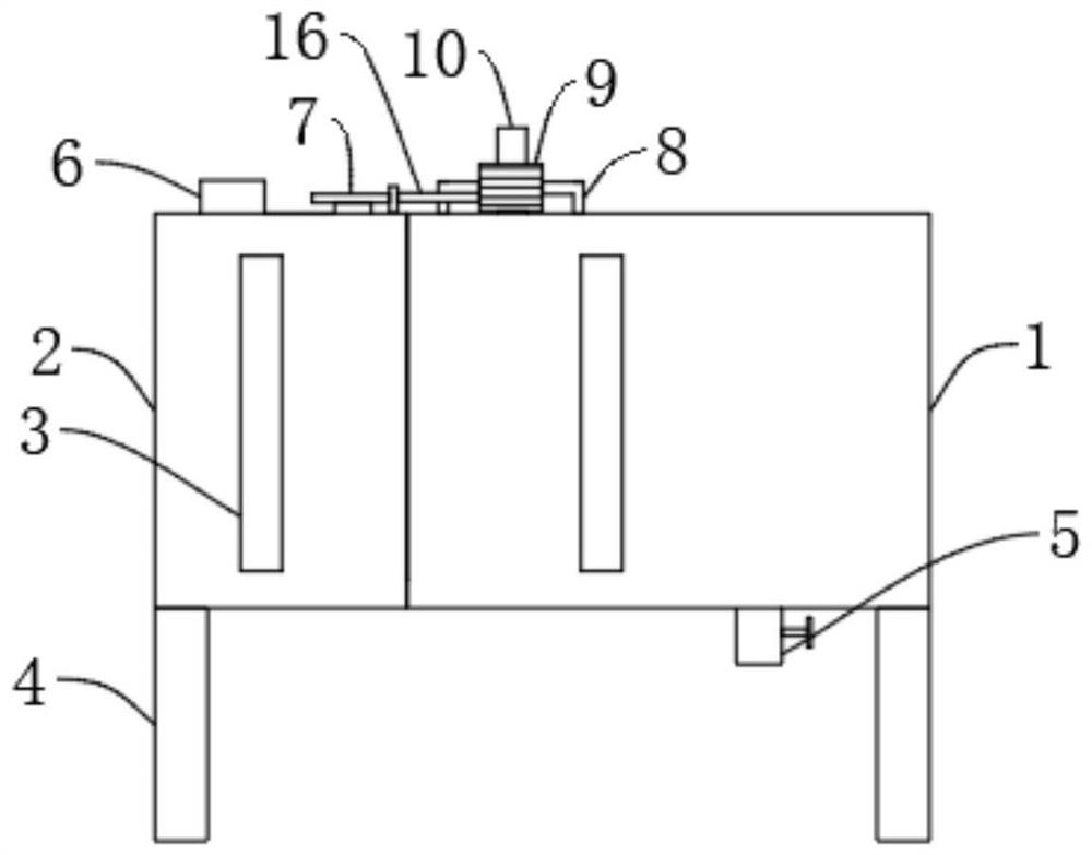
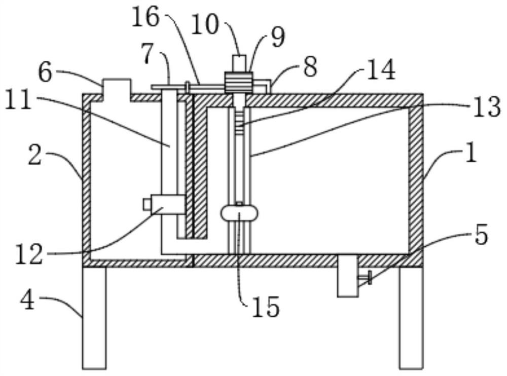
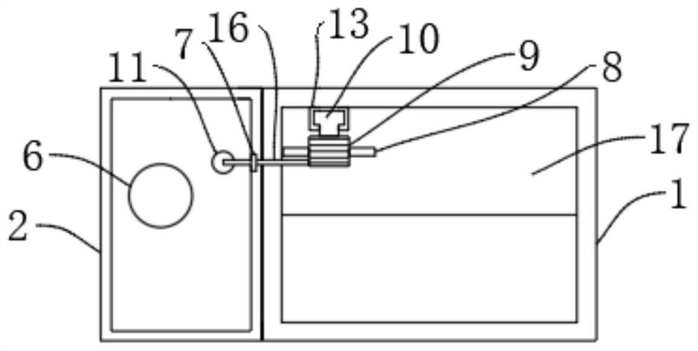
[0027] Embodiment one, by figure 1 , figure 2 and image 3 Provided, the present invention is an electrolytic cell liquid level automatic adjustment device, comprising an electrolytic cell 1, the left side of the electrolytic cell 1 is fixedly connected with a supplementary liquid tank 2, and the inner cavity of the supplementary liquid tank 2 is fixedly connected with a water pipe 11, and the water pipe 11 is connected to the electrolytic cell 1 is connected, the surface of the water pipe 11 is clamped with the water pump 12, the top of the water pipe 11 is fixedly connected with the switch 7, the rear surface of the inner wall of the electrolytic cell 1 is slidingly connected with the expansion plate 10, the surface of the expansion plate 10 is fixedly connected with the rack 14, and the bottom of the expansion plate 10 The buoy 15 is clamped, the top of the electrolytic cell 1 is provided with a gear 9, the gear 9 meshes with the rack 14, the left side of the gear 9 is fi...

Embodiment 2

[0028] Embodiment two, on the basis of embodiment one, by image 3 Given, the surface of the electrolytic cell 1 is clamped with a support plate 17 , the surface of the support plate 17 is fixedly connected with a fixed rod 8 , the fixed rod 8 is in an inverted U shape, and the fixed rod 8 is rotatably connected with the gear 9 .

[0029] The support plate 17 is designed to support the fixed rod 8, and the fixed rod 8 is designed to install the gear 9 to facilitate its rotation.

Embodiment 3

[0030] Embodiment three, on the basis of embodiment one, by figure 2 Given, the rear side of the inner wall of the electrolytic cell 1 is fixedly connected with a fixed block 13, the surface of the fixed block 13 is provided with a chute, the chute is T-shaped, and the telescopic plate 10 is slidably connected to the inner cavity of the chute, and the material of the telescopic plate 10 is light plastic.

[0031] The design of the chute is convenient for the telescopic plate 10 to slide, and the material of the telescopic plate 10 is light plastic so that the telescopic plate 10 can expand and contract with the buoyancy of the electrolyte.


PUM


Abstract

The invention relates to the technical field of electrolytic cells, and discloses an automatic electrolytic cell liquid level adjusting device. The automatic electrolytic cell liquid level adjusting device comprises an electrolytic cell. A replenishing liquid tank is fixedly connected to the left side of the electrolytic cell, a water pipe is fixedly connected to an inner cavity of the replenishing liquid tank and communicates with the electrolytic cell, a water pump is clamped to the surface of the water pipe, and a switch is fixedly connected to the top of the water pipe. A telescopic plateis slidably connected to the surface of the rear side of the inner wall of the electrolytic cell, a rack is fixedly connected to the surface of the telescopic plate, a buoy is clamped to the bottom ofthe telescopic plate, a gear is arranged at the top of the electrolytic cell, the gear is meshed with the rack, and a connecting rod is fixedly connected to the left side of the gear. When the liquidlevel of electrolyte descends, the electrolyte is supplemented in time, waste of an anode is avoided, the concentration of the electrolyte can be kept, the electrolyte does not need to be checked andsupplemented manually all the time, the manual labor amount is reduced, and the working efficiency is improved.

Description

technical field [0001] The invention belongs to the technical field of electrolytic cells for zinc hydrometallurgy, in particular to an automatic liquid level regulator for electrolytic cells. Background technique [0002] At present, 80% of domestic zinc is produced by hydrometallurgical process. The final process of zinc wet extraction process is zinc electrolytic deposition, that is, zinc is precipitated from zinc sulfate solution to the cathode, and then cast into zinc ingot products. [0003] The ammonia electrolytic zinc process is one of the important methods for producing zinc metal. It has the advantages of good material adaptability, low raw material price, simple process flow and low cost, and is especially suitable for secondary zinc-containing materials. Such as zinc-containing electric arc furnace dust, gas ash and zinc subchloride. However, in the existing ammonia-based electrolytic zinc process, there are still problems in the following aspects: [0004] (1...

Claims


Application Information

Patent Timeline
Patent Type & Authority Applications(China)
IPC IPC(8): C25C1/16C25C7/00C25C7/06
CPCC25C1/16C25C7/00C25C7/06Y02P10/20
Inventor 吴春晗张栋张露张海啸
Owner 宁夏鼎辉科技有限公司
Why Eureka
Try Eureka