Supercharge Your Innovation With Domain-Expert AI Agents!

Radial-flow secondary sedimentation device and sludge regeneration method

A radial flow and sludge technology, applied in the adjustment method of biological treatment, the feeding/discharging device of the settling tank, the separation method, etc., can solve the problems of increased construction costs, save land costs, and reduce equipment purchases And, the effect of reducing the return flow of sludge

Active Publication Date: 2021-08-24
CENT & SOUTHERN CHINA MUNICIPAL ENG DESIGN & RES INST
View PDF6 Cites 0 Cited by
  • Summary
  • Abstract
  • Description
  • Claims
  • Application Information

AI Technical Summary

Problems solved by technology

[0006] The purpose of the present invention is to solve the problem of increased construction cost of sewage treatment plants that currently use sludge regeneration tanks to activate activated sludge

Method used


Image

  • Radial-flow secondary sedimentation device and sludge regeneration method
  • Radial-flow secondary sedimentation device and sludge regeneration method
  • Radial-flow secondary sedimentation device and sludge regeneration method

Examples


Embodiment 1

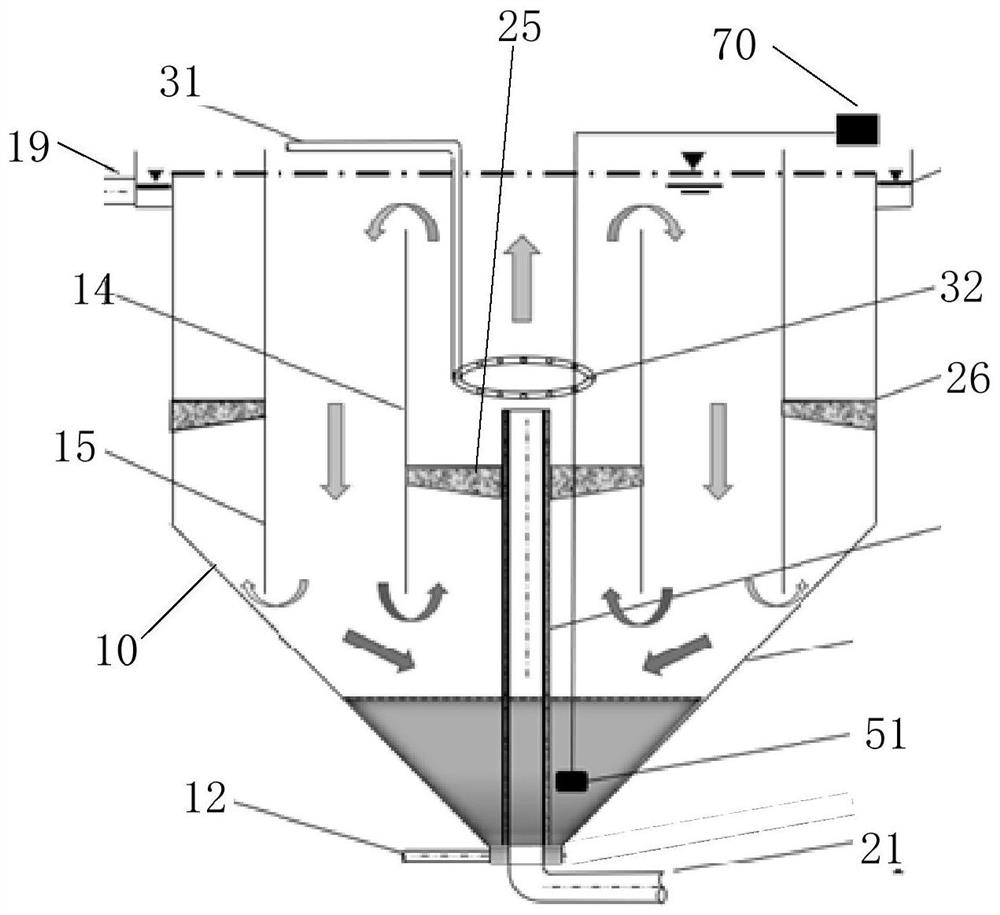
[0035] refer to figure 1 , the present invention proposes a radial flow secondary settling device, comprising a tank body 10, an inner cylinder 14, an outer cylinder 15, and a water inlet pipe 21; the upper end of the tank body 10 is open, and the lower end is closed to form a slope for accumulating sludge ; the inner cylinder 14 is arranged in the tank body 10, and is vertically connected, and the inside of the inner cylinder 14 forms an aeration area; the outer cylinder 15 is arranged on the outer periphery of the inner cylinder 14, and the outer cylinder 15 and the inner cylinder The area between the cylinders 14 forms a circulation area, and the area between the outer cylinder 15 and the tank body 10 forms a drainage area; the water inlet pipe 21 is arranged in the tank body 10; the aeration assembly is arranged in the Aeration zone.

[0036] Specifically, the water inlet pipe 21 extends upwards from the lower part of the tank body 10 to the aeration area, and the outer p...

Embodiment 2

[0040] refer to figure 1 The radial flow secondary sedimentation device also includes an aeration assembly, the aeration assembly includes an aeration element 32 arranged in the aeration area and an air inlet pipe 31 communicated with the aeration element 32, the aeration element 32 Air holes are arranged on it. The air inlet pipe 31 is inserted into the aeration area from the upper end of the tank body 10, and the aeration element 32 is an annular pipe or a spiral pipe. The aeration element 32 is located above the water outlet of the water inlet pipe 21, and is generally arranged in the middle and lower half of the aeration area.

[0041] In this embodiment, the sewage with sludge is input into the tank body 10, and the aeration component blows air in the aeration zone, and the generated air bubbles make the sewage rise and enter the upper part of the circulation zone; The circulation area sinks to the bottom of the tank body 10 and is drawn out from the sewage outlet at th...

Embodiment 3

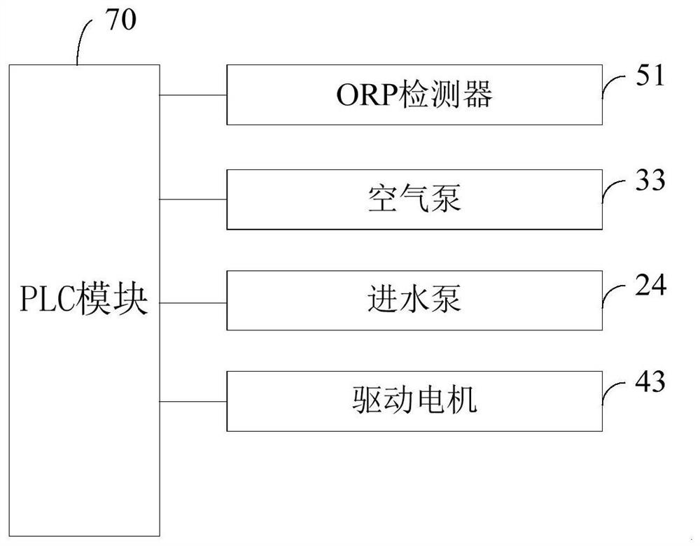
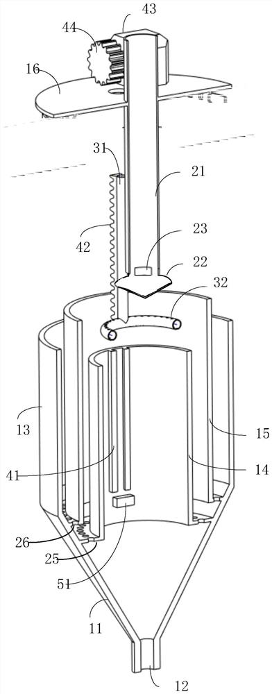
[0045] refer to figure 2 with image 3 , the present invention proposes a radial flow secondary sedimentation device, including: PLC module 70, ORP detector 51, tank body, inner cylinder 14, outer cylinder 15, aeration assembly and water inlet pipe 21, first lifting assembly and water inlet pipe twenty one. The lower end of the tank body 1 is closed to form a dirt collecting bucket 11, and the outer wall of the tank body is cylindrical. The inner cylinder 14 is also cylindrical, forming an aeration zone inside the inner cylinder 14; the outer cylinder 15 is cylindrical, extending upward from the inner wall of the sewage collection bucket 11, and is located between the outer shell 13 and the inner cylinder. 14, the outer cylinder 15 is higher than the inner cylinder 14; the cover 16 is arranged on the outer cylinder 15; the settling hole is arranged at the bottom of the inner cylinder 14 and the outer cylinder 15; the inner cylinder 14 and the outer cylinder 15 The area bet...


PUM


Abstract

The invention discloses a radial-flow secondary sedimentation device and a sludge regeneration method. The radial-flow secondary sedimentation device comprises a tank body, an inner cylinder, an outer cylinder, an aeration assembly and a water inlet pipe; the lower end of the tank body is closed to form an inclined surface for gathering sludge; the inner cylinder is arranged in the tank body and is through vertically, and an aeration area is formed in the inner cylinder; the outer cylinder is arranged on the periphery of the inner cylinder, a circulation area is formed in the area between the outer cylinder and the inner cylinder, and a drainage area is formed in the area between the outer cylinder and the tank body; the water inlet pipe is arranged in the tank body; and the aeration assembly is arranged in the aeration area. According to the invention, the sludge is activated and regenerated in an aeration manner, so that the sludge from a biochemical pool can be activated and regenerated under a micro-aerobic condition, the denitrification capacity of a sewage treatment system is improved, the condition that the sludge releases phosphorus again in the device is reduced, the sludge reflux quantity is reduced, and the additional operation cost caused by the increase of the reflux quantity can be effectively reduced.

Description

technical field [0001] The invention belongs to the field of sewage treatment, and in particular relates to a radial-flow secondary settling device and a sludge regeneration method. Background technique [0002] In the sewage treatment process, the functional microorganisms of the activated sludge determine the nitrogen and phosphorus removal performance of the sewage treatment system. The growth and metabolism of microorganisms are divided into adaptation period, logarithmic growth period, stable period and decline period. The sludge in the stable period in the sewage treatment system has the most obvious degradation effect on COD, nitrogen and phosphorus in the water body. (The main primary metabolism is parallel to the growth process of the bacteria) Therefore, keeping the sludge in a stable period with relatively efficient degradation ability is of great significance for the denitrification and phosphorus removal of water bodies. [0003] The activated sludge method is ...

Claims


Application Information

Patent Timeline
IPC IPC(8): B01D21/00B01D21/02B01D21/24B01D21/30C02F3/00C02F3/30
CPCB01D21/003B01D21/10B01D21/2405B01D21/302B01D21/0084C02F3/006C02F3/30C02F2209/005C02F2209/04Y02W10/10
Inventor 董文艺谢晋刘华光侯子泷黎柳记刘向荣戴仲怡
Owner CENT & SOUTHERN CHINA MUNICIPAL ENG DESIGN & RES INST
Features
  • R&D
  • Intellectual Property
  • Life Sciences
  • Materials
  • Tech Scout
  • Unparalleled Data Quality
  • Higher Quality Content
  • 60% Fewer Hallucinations
Learn More