A uniform drying device for electroplating parts

A technology for drying devices and electroplating parts, which is applied in drying, dryers, heating devices, etc., which can solve the problems of low heat utilization and no hydrogen ion diffusion, and achieve good water and hydrogen removal effects and strong adsorption performance, speed-up effects

Active Publication Date: 2022-05-24
柳州市荣鑫金属表面处理有限公司
View PDF2 Cites 0 Cited by
  • Summary
  • Abstract
  • Description
  • Claims
  • Application Information

AI Technical Summary

Problems solved by technology

[0004] The purpose of the present invention is to provide a uniform drying device for electroplated parts, which solves the problem that the drying device for electroplated parts in the prior art has a low utilization rate of heat and the drying device does not handle the diffusion of hydrogen ions

Method used


Image

  • A uniform drying device for electroplating parts

Examples


Embodiment 1

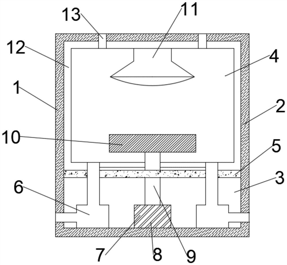
[0045] A device for uniform drying of electroplated parts, such as figure 1 As shown, the drying device body 1 is included, and the outer shell 2 of the drying device body 1 is separated by a thermal insulation layer 5 to form a heating cavity 3 and a constant temperature cavity 4. The heating cavity 3 and the constant temperature cavity 4 pass through the thermal insulation layer 5. Separated; the heating cavity 3 is provided with a blowing device 6 and a rotating device 7, the rotating device 7 is fixed at the bottom of the heating cavity 3, and the blowing device 6 is arranged on both sides of the rotating device 7; one end of the blowing device 6 The side wall of the heating cavity 3 communicates with the outside world, and the other end communicates with the constant temperature cavity 4 through the thermal insulation layer 5; the rotating device 7 includes a motor 8 and a rotating shaft 9, and the rotating shaft 9 passes through the thermal insulation layer 5 and extends ...

Embodiment 2

[0061] A device for uniform drying of electroplated parts, such as figure 1 As shown, the drying device body 1 is included, and the outer shell 2 of the drying device body 1 is separated by a thermal insulation layer 5 to form a heating cavity 3 and a constant temperature cavity 4. The heating cavity 3 and the constant temperature cavity 4 pass through the thermal insulation layer 5. Separated; the heating cavity 3 is provided with a blowing device 6 and a rotating device 7, the rotating device 7 is fixed at the bottom of the heating cavity 3, and the blowing device 6 is arranged on both sides of the rotating device 7; one end of the blowing device 6 The side wall of the heating cavity 3 communicates with the outside world, and the other end communicates with the constant temperature cavity 4 through the thermal insulation layer 5; the rotating device 7 includes a motor 8 and a rotating shaft 9, and the rotating shaft 9 passes through the thermal insulation layer 5 and extends ...

Embodiment 3

[0077] A device for uniform drying of electroplated parts, such as figure 1 As shown, the drying device body 1 is included, and the outer shell 2 of the drying device body 1 is separated by a thermal insulation layer 5 to form a heating cavity 3 and a constant temperature cavity 4. The heating cavity 3 and the constant temperature cavity 4 pass through the thermal insulation layer 5. Separated; the heating cavity 3 is provided with a blowing device 6 and a rotating device 7, the rotating device 7 is fixed at the bottom of the heating cavity 3, and the blowing device 6 is arranged on both sides of the rotating device 7; one end of the blowing device 6 The side wall of the heating cavity 3 communicates with the outside world, and the other end communicates with the constant temperature cavity 4 through the thermal insulation layer 5; the rotating device 7 includes a motor 8 and a rotating shaft 9, and the rotating shaft 9 passes through the thermal insulation layer 5 and extends ...


PUM

PropertyMeasurementUnit
thicknessaaaaaaaaaa

Abstract

The invention discloses a uniform drying device for electroplating parts, which comprises a drying device body. The inner cavity of the drying device body is separated by an insulating layer to form a heating cavity and a constant temperature cavity. The compartments are separated; the heating chamber is equipped with a blowing device and a rotating device, the rotating device is fixed at the bottom of the heating chamber, and the blowing device is arranged on both sides of the rotating device; the top of the constant temperature chamber is provided with an infrared heating lamp, The inner wall is provided with a thermal insulation lining, and the material of the thermal insulation lining is nano airgel material. On the basis of the existing drying device, the present invention sets the heating plate in the constant temperature chamber and adds a thermal insulation lining. The thermal insulation lining of the present invention can not only maximize the utilization of heat, but also make the temperature in the drying device It is isolated from the outside world and can absorb water molecules and hydrogen molecules, so that the electroplated parts can get better water and hydrogen removal effects, and the precipitated water vapor or hydrogen will not be adsorbed on the electroplated parts again.

Description

technical field [0001] The invention relates to the field of electroplated parts, in particular to a device for uniform drying of electroplated parts. Background technique [0002] As in the electroplating production, the workpiece needs to be cleaned after electroplating to remove the residual plating solution on the surface of the workpiece, and after cleaning, the surface of the electroplated parts still has water remaining. The electroplated parts need to be dried. [0003] The traditional drying method is air drying, but this method occupies a large space, and the speed is slow, and the surface of the electroplated parts is easy to adhere to dust, and the drying device is used for drying. This method often has low heat utilization rate, so it needs to pass The plated parts are dried by raising the higher temperature, but some plated parts cannot be processed at too high temperature, which must prolong the drying time. At the same time, the reason why the electroplated...

Claims


Application Information

Patent Timeline
Patent Type & Authority Patents(China)
IPC IPC(8): C25D5/48C21D3/06F26B11/18F26B21/00F26B23/04F26B25/02F26B25/04C01B19/04C01B33/158B82Y40/00B82Y30/00
CPCC25D5/48C21D3/06F26B11/18F26B21/003F26B23/04F26B25/02F26B25/04C01B19/007C01B33/1585B82Y40/00B82Y30/00C01P2004/80
Inventor 赖广培覃勇志韦矿东
Owner 柳州市荣鑫金属表面处理有限公司
Why Eureka
Try Eureka