
Multi-element multi-effect absorption heat pump

An absorption heat pump and heat pump technology, applied in the field of heat pumps, can solve the problems of large distillation pressure difference, shorten unit life, reduce phase change heat transfer efficiency, etc., and achieve the effect of increasing condensation temperature, reducing working temperature difference, and increasing the number of stages

Active Publication Date: 2021-08-24
闫广
View PDF6 Cites 0 Cited by
  • Summary
  • Abstract
  • Description
  • Claims
  • Application Information

AI Technical Summary

Problems solved by technology

In order to improve the reabsorption of water, the lithium bromide absorption heat pump generally has a very high solution concentration (the original solution is generally not less than 30%, and the absorbent state is more than 60%), that is, the boiling point of the lithium bromide solution is raised when the high temperature heat energy is used to distill the lithium bromide solution. Exceeding 60°C, the extremely high degree of superheat makes it difficult to apply multi-effect evaporation technology, and the distillation pressure difference between the two stages is particularly large, so that multi-effect evaporation cannot be achieved under a limited temperature difference
[0006] On the other hand, lithium bromide solution and ammonia solution have a particularly strong corrosion effect on metals at high temperatures. Lithium bromide solution should not exceed 140 ° C. When ammonia solution reaches 90 ° C, relatively strong alkali corrosion will occur, which will corrode steel inside and produce hydrogen gas. A non-condensable gas, which shortens the life of the unit and reduces the efficiency of phase change heat transfer
This is also the reason why the absorption heat pump cannot increase the temperature of the cycle to achieve a lot of efficiency.

Method used


Image

  • Multi-element multi-effect absorption heat pump

Examples


Embodiment Construction

[0034] The technical solutions in the embodiments of the present invention will be clearly and completely described below in conjunction with the accompanying drawings in the embodiments of the present invention. Apparently, the described embodiments are only some of the embodiments of the present invention, not all of them. Based on the embodiments of the present invention, all other embodiments obtained by persons of ordinary skill in the art without making creative efforts all belong to the protection scope of the present invention.

[0035] In describing the present invention, it should be understood that the terms "upper", "lower", "front", "rear", "left", "right", "top", "bottom", "inner", " The orientation or positional relationship indicated by "outside", etc. is based on the orientation or positional relationship shown in the drawings, and is only for the convenience of describing the present invention and simplifying the description, rather than indicating or implying...


PUM


Abstract

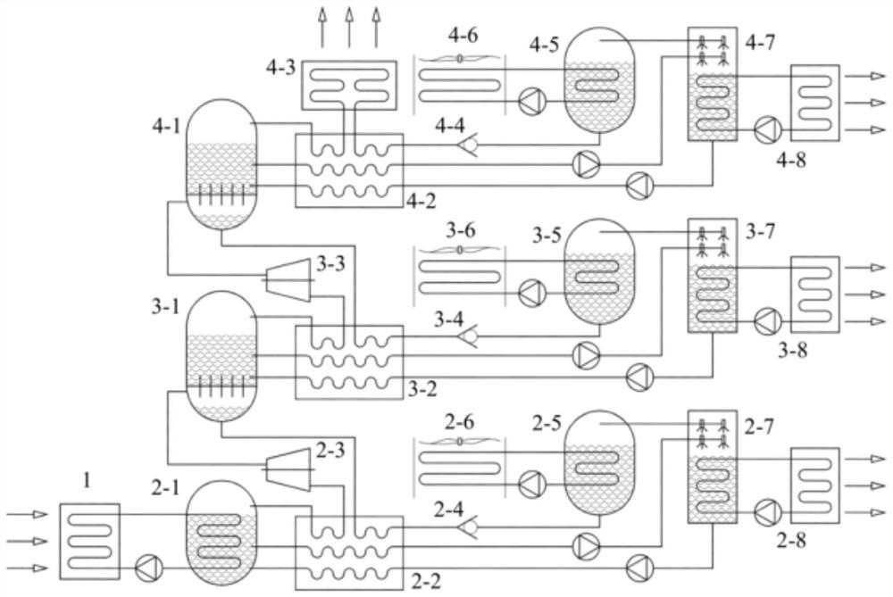
The invention discloses a multi-element multi-effect absorption heat pump. The multi-element multi-effect absorption heat pump comprises a heat exchanger and multiple stages of heat pump circulation systems; wherein each stage of heat pump circulation system comprises a distillation retort, a heat regenerator, a pressure reducing valve, an evaporator, an absorption tower and a heat conduction piece; in any two adjacent stages of heat pump circulation systems, a steam outlet of the heat regenerator of the heat pump circulation system located at the upper stage communicates with the distillation retort of the heat pump circulation system located at the lower stage through a pipeline and provides a heat source for the heat pump circulation system located at the lower stage; and the heat source located in the first-stage heat pump circulation system is external high-temperature heat energy, and the high-temperature heat energy heats an original solution in the distillation retort of the first-stage heat pump circulation system through the heat exchanger. According to the multi-element multi-effect absorption heat pump provided by the invention, the heat source is provided for the lower-stage heat pump circulation system through the upper-stage heat pump circulation system, so that the heat pump efficiency is improved.

Description

technical field [0001] The invention relates to the technical field of heat pumps, in particular to a multi-element and multi-effect absorption heat pump. Background technique [0002] The structure of the heat pump is complicated, the heat exchange area is large, the price of the absorbent and the refrigerant is also relatively expensive, the cost of the heat source is too high, the initial investment is high, and the cost-effectiveness ratio is really poor. For example, the calorific value of the gas-driven ammonia-water absorption heat pump and the low-nitrogen condensing gas-fired boiler do not show advantages, and the economic benefits are even lower than the latter. Compared with the economic benefits of heating projects with other fuels, the benefits of gas heat pumps are worse. Therefore, in order to improve the energy efficiency of the heat pump, the heat pump must be improved and upgraded to improve the efficiency of the heat pump. [0003] At present, the transf...

Claims


Application Information

Patent Timeline
IPC IPC(8): F25B30/04
CPCF25B30/04Y02B30/52
Inventor 闫广陈兴彩郭会军张亚琼张雄洲
Owner 闫广
Learn More