Air energy expanded rock fracturing system and using method thereof

An air energy and fracturing technology, which is applied in earth drilling, offensive equipment, blasting barrels, etc., can solve problems such as excessive carbon dioxide in the workplace and suffocation of staff, and achieve low construction costs, no noise pollution, and high safety.

Pending Publication Date: 2021-08-24
席绍辉
View PDF5 Cites 0 Cited by
  • Summary
  • Abstract
  • Description
  • Claims
  • Application Information

AI Technical Summary

Problems solved by technology

If the air is released in a closed space, the carbon dioxide in the workplace may exceed the standard, and even cause the staff to suffocate

Method used


Image

  • Air energy expanded rock fracturing system and using method thereof
  • Air energy expanded rock fracturing system and using method thereof
  • Air energy expanded rock fracturing system and using method thereof

Examples


Embodiment 1

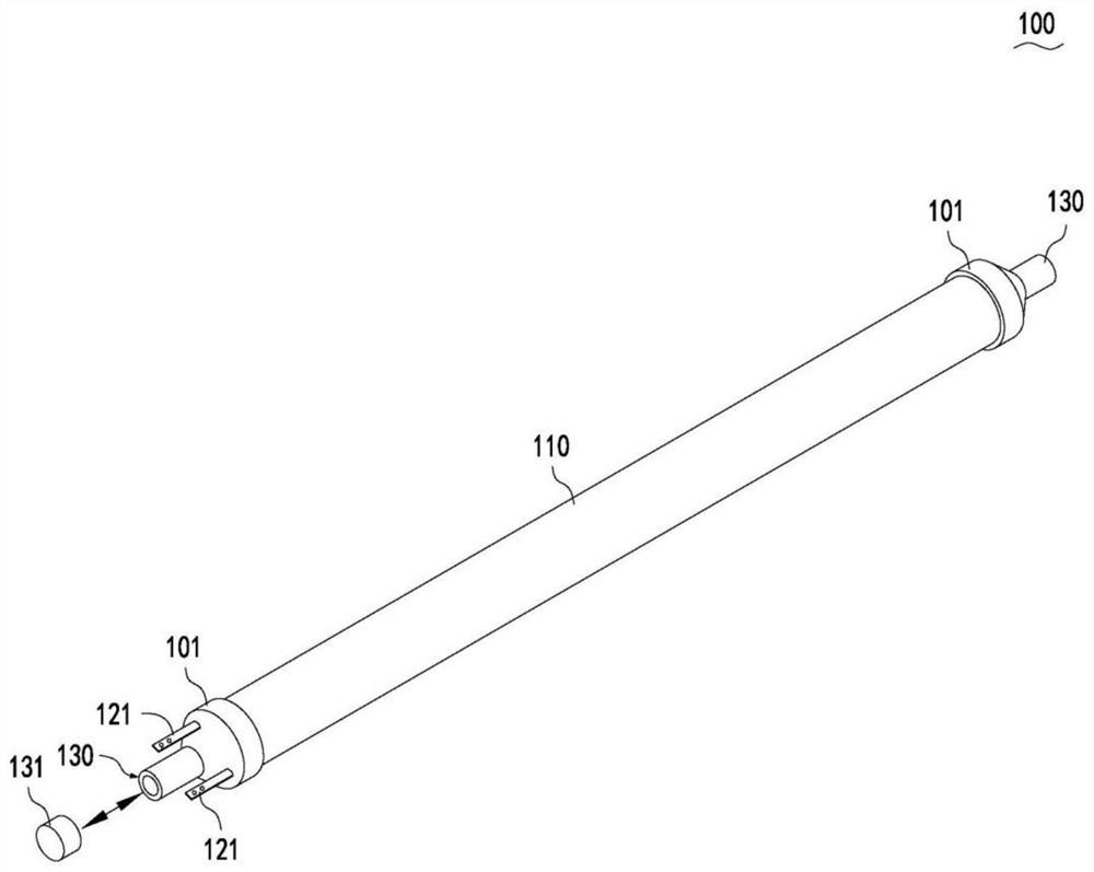
[0033] Such as Figure 1 to Figure 4 As shown, an air-expandable rock fracturing system according to a preferred embodiment of the present invention is used to fracturing rock through an air medium.

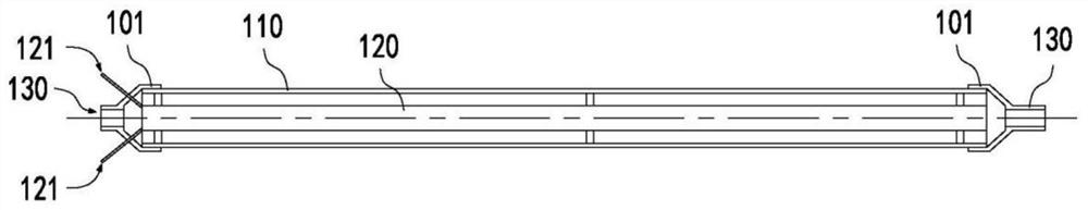
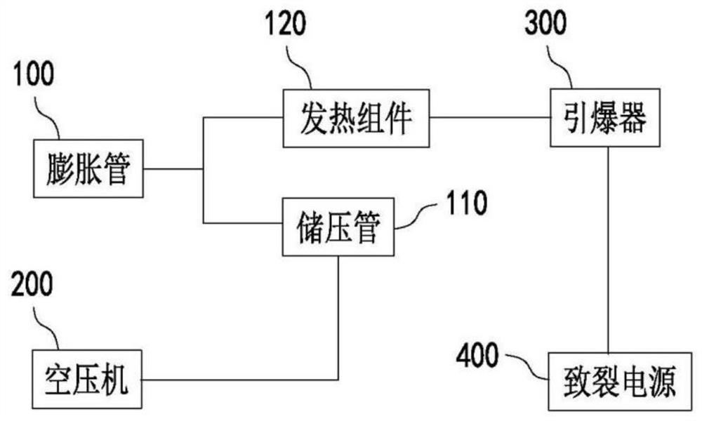
[0034] Based on the above technical solution, this embodiment provides an air energy expandable rock fracturing system, including an expansion tube 100, an air compressor 200, a detonator 300, and a fracturing power supply 400. The expansion tube 100 includes a pressure storage tube 110, a heating component 120 , the expansion tube 100 seals the heating component 120 inside, the air compressor 200 can be connected to the pressure storage tube 110 through a pipeline, and the heating component 120 can be connected to the cracking power supply 400 through the detonator 300 .

[0035] Wherein, the expansion tube 100 is a direct working component of expansion fracturing. The heating component 120 is used for heating and pressurizing the expansion tube 100 in the expansion tube 100 , ...

Embodiment 2

[0049] The general working sequence of the steps used for the fracturing system in Example 1 is: drilling holes at the construction site—assembling the expansion pipe—installing expansion—blocking with special cement—pressurizing high-pressure gas during expansion—expanding - Clean up the working surface.

[0050] Specifically, such as Figure 5 As shown, the present invention provides a method for using an air-expandable rock fracturing system, comprising the following steps:

[0051] S100. Drill holes on the rock and clean them, place expansion tubes 100 in the holes and seal the holes with quick-drying cement until the cement reaches the solidification strength. Here, the drilling depth has nothing to do with the rock grade, but is determined by the geographical environment; the drilling size has nothing to do with the rock grade, and only the expansion tube can be placed; there is no need to drain the water, and the requirements for the rock hole are not high. Therefore,...


PUM


Abstract

The invention relates to the technical field of blasting, and discloses an air energy expanded rock fracturing system which comprises expansion pipes, an air compressor, blasting units and a fracturing power source. Each expansion pipe comprises a pressure storage pipe and a heating assembly, each heating assembly is sealed in the corresponding expansion pipe, and the air compressor can be connected with the pressure storage pipe through a pipeline; and the heating assemblies can be connected with the fracturing power source through the blasting units. The invention further provides a using method of the air energy expanded rock fracturing system. The using method comprises the following steps that holes are drilled in rock, distributed and cleaned, the expansion pipes are placed in the holes, and the holes are plugged with quick-setting cement until the cement reaches the solidification strength; air is pressurized into the expansion pipes, blocking and pressure maintaining are carried out, and all expansion pipes are connected to the fracturing power supply through the blasting units by using leads; and people are evacuated, and the working surface is cleaned after the rock is expanded and fractured. The air energy expanded rock fracturing system and the using method are high in safety, and the construction cost is greatly reduced.

Description

technical field [0001] The invention relates to the technical field of blasting, in particular to an air energy expandable rock fracturing system and its application method. Background technique [0002] As we all know, explosive blasting is one of the main reasons for major accidents. In other fields, explosive blasting often causes great damage to surrounding buildings and personnel. For example, it causes the collapse of buildings, the damage of power transmission lines, and even the loss of human life. This is determined by the characteristics of explosives. The explosion process of explosives is completed in a very short moment, and the instantaneous chemical reaction produces a strong impact force (above 1000Mpa-5000Mpa). It can form a strong vibration, reaching the intensity of "earthquake above magnitude 3". [0003] There are fracturing systems that use carbon dioxide as the fracturing medium. From a physical point of view, carbon dioxide is already existing and ...

Claims


Application Information

Patent Timeline
Patent Type & Authority Applications(China)
IPC IPC(8): F42B3/04E21C37/14
CPCF42B3/04E21C37/14
Inventor 席绍辉
Owner 席绍辉
Why Eureka
Try Eureka