Modeling method for aerodynamic model of turbomachinery blade

A technology of aerodynamic model and impeller machinery, applied in 3D modeling, image data processing, special data processing applications, etc., can solve the problems of taking up a lot of personal energy, high modeling accuracy, and long time consumption, so as to reduce eye fatigue , large time gain, simple setting effect

Active Publication Date: 2021-08-24
上海尚实航空发动机股份有限公司
View PDF5 Cites 1 Cited by
  • Summary
  • Abstract
  • Description
  • Claims
  • Application Information

AI Technical Summary

Problems solved by technology

[0005] The purpose of the present invention is to provide a modeling method for the aerodynamic model of turbomachinery blades, which solves the problems of the existing aerodynamic modeling methods such as long time-consuming, taking up a lot of personal energy, and being prone to errors under the condition of ensuring the modeling accuracy. The mechanical blade quickly carries out aerodynamic model modeling, the modeling time is short, and the modeling accuracy is high; the operator does not have to deal with a large amount of data, which can effectively reduce eye fatigue

Method used


Image

  • Modeling method for aerodynamic model of turbomachinery blade
  • Modeling method for aerodynamic model of turbomachinery blade
  • Modeling method for aerodynamic model of turbomachinery blade

Examples


Embodiment Construction

[0033] The present invention will be described in further detail below in conjunction with the accompanying drawings and embodiments. It should be understood that the specific embodiments described here are only used to explain the present invention, but not to limit the present invention. In addition, it should be noted that, for the convenience of description, only some structures related to the present invention are shown in the drawings but not all structures.

[0034] In the description of the present invention, unless otherwise clearly specified and limited, the terms "connected", "connected" and "fixed" should be understood in a broad sense, for example, it can be a fixed connection, a detachable connection, or an integrated ; It can be a mechanical connection or an electrical connection; it can be a direct connection or an indirect connection through an intermediary, and it can be the internal communication of two components or the interaction relationship between two ...


PUM


Abstract

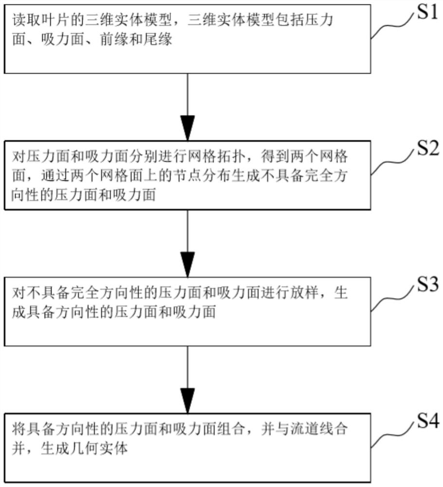
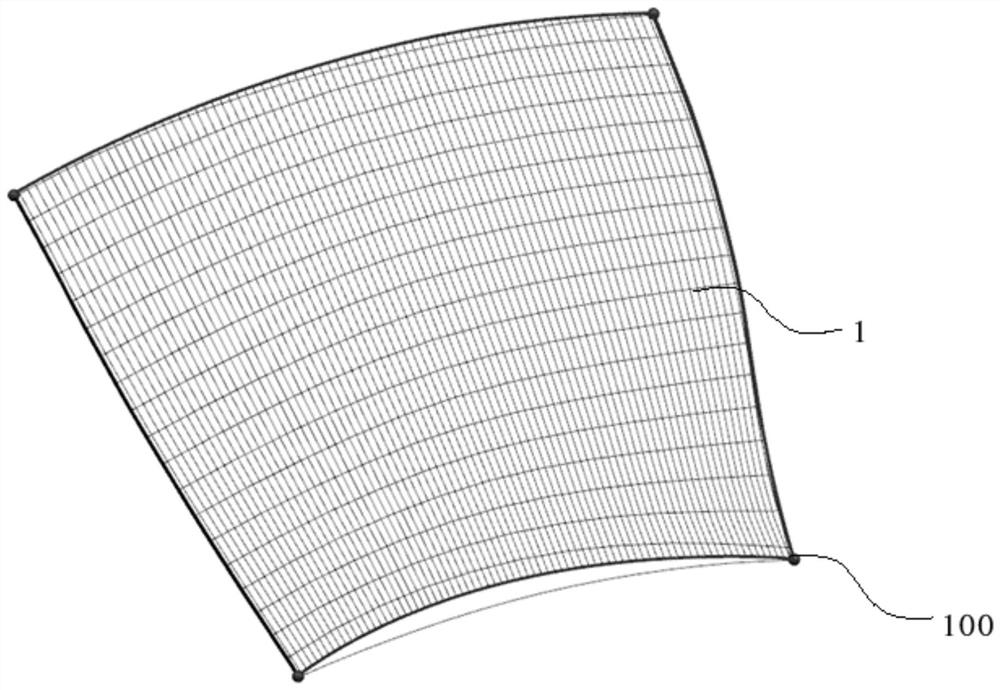
The invention belongs to the technical field of pneumatic models of turbomachinery, and particularly relates to a modeling method for an aerodynamic model of a turbomachinery blade, which comprises the following steps of: S1, reading a three-dimensional solid model of the blade, including a pressure surface, a suction surface, a front edge and a tail edge; s2, performing grid topology on the pressure surface and the suction surface to obtain two grid surfaces, and generating the pressure surface and the suction surface which do not have complete directivity through node distribution on the grid surfaces; s3, lofting the pressure surface and the suction surface which do not have the complete directivity, and generating the pressure surface and the suction surface which have the directivity; and S4, combining the pressure surface and the suction surface with directivity, and combining the pressure surface and the suction surface with the runner line to generate a geometric entity. According to the modeling method, the distribution of the point set on each blade height section is replaced by the distribution of the grid nodes on the pressure surface and the suction surface, so that the aerodynamic model can be quickly established for the blade, and the modeling precision is high; and the eye fatigue can be effectively relieved without processing a large amount of data.

Description

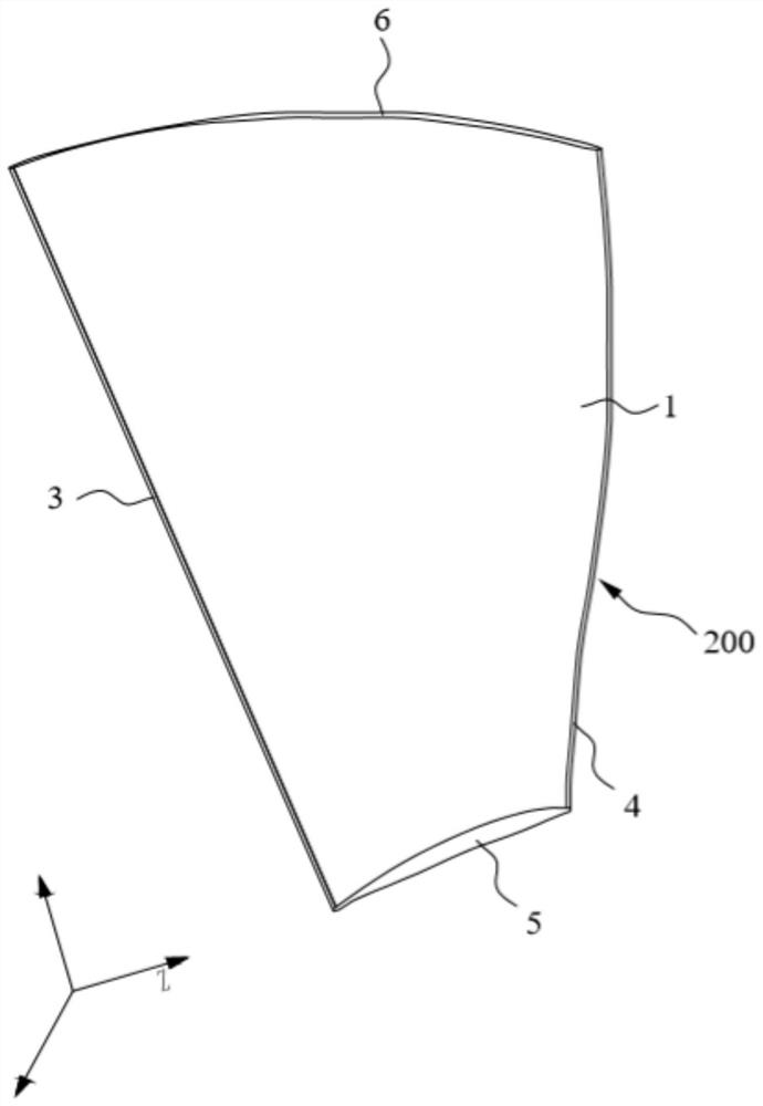
technical field [0001] The invention relates to the technical field of turbomachine aerodynamic models, in particular to a modeling method for the aerodynamic model of a turbomachine blade. Background technique [0002] The premise of the numerical calculation of the aerodynamic performance of turbomachinery is to perform grid topology on the aerodynamic model. There are many grid generation software and programs for turbomachinery in the market, which can generate structured grids conveniently and quickly. However, most of these grid generation software or programs have relatively strict requirements on 3D models or numerical models, or require a concise and accurate 3D blade model, or require data points arranged in a certain format that can represent blades. [0003] The three-dimensional solid model of turbomachinery blades is usually obtained by cutting and stitching various sheets and surfaces. When docking with the mesh generation software, some processed lines or sur...

Claims


Application Information

Patent Timeline
Patent Type & Authority Applications(China)
IPC IPC(8): G06F30/23G06F30/28G06T17/20G06F119/14
CPCG06F30/23G06F30/28G06T17/20G06F2119/14
Inventor 马亚茹陈波周翔王进王石柱
Owner 上海尚实航空发动机股份有限公司
Why Eureka
Try Eureka