Grinding and polishing clamp for stainless steel part machining and machining technology of grinding and polishing clamp

A polishing jig and stainless steel technology, which is applied in the direction of grinding/polishing equipment, manufacturing tools, metal processing equipment, etc., can solve the problems of uneven grinding quality, low work efficiency, high operation requirements, etc., achieve high work efficiency and improve utilization The effect of high efficiency and safety

Pending Publication Date: 2021-08-27
江门市弈创科技有限公司
View PDF0 Cites 3 Cited by
  • Summary
  • Abstract
  • Description
  • Claims
  • Application Information

AI Technical Summary

Problems solved by technology

[0003] In the prior art, when grinding stainless steel pipe fittings, most of the pipe fittings are clamped from the outside, and then polished and polished by hand-held grinding equipment. This operation method has high requirements for the operation of the staff, and the work efficiency is low, and the grinding quality is uneven. uneven, poor security, therefore, the inventors have proposed a grinding and polishing jig for processing stainless steel parts and its processing technology

Method used


Image

  • Grinding and polishing clamp for stainless steel part machining and machining technology of grinding and polishing clamp
  • Grinding and polishing clamp for stainless steel part machining and machining technology of grinding and polishing clamp
  • Grinding and polishing clamp for stainless steel part machining and machining technology of grinding and polishing clamp

Examples


Embodiment Construction

[0029] In order to make the technical means, creative features, goals and effects achieved by the present invention easy to understand, the present invention will be further described below in conjunction with specific embodiments.

[0030] In the description of the present invention, it should be noted that the terms "upper", "lower", "inner", "outer", "front end", "rear end", "both ends", "one end", "another end" The orientation or positional relationship indicated by etc. is based on the orientation or positional relationship shown in the drawings, and is only for the convenience of describing the present invention and simplifying the description, rather than indicating or implying that the referred device or element must have a specific orientation, use a specific Azimuth configuration and operation, therefore, should not be construed as limiting the invention. In addition, the terms "first" and "second" are used for descriptive purposes only, and should not be understood ...


PUM


Abstract

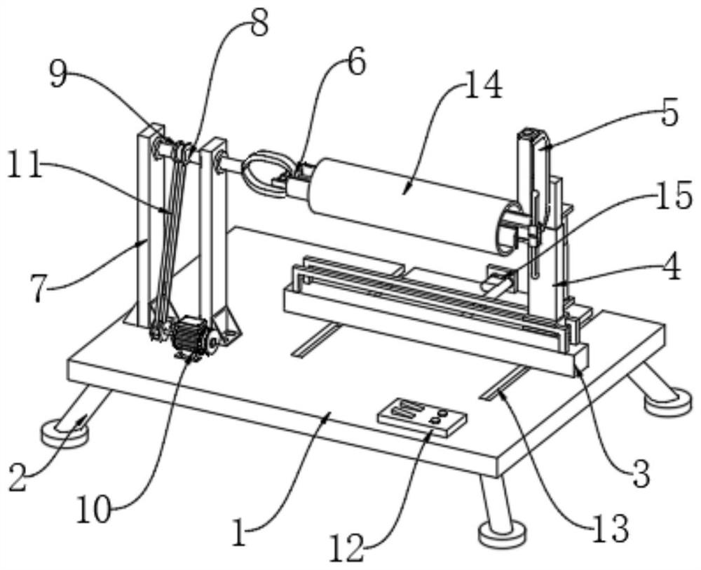
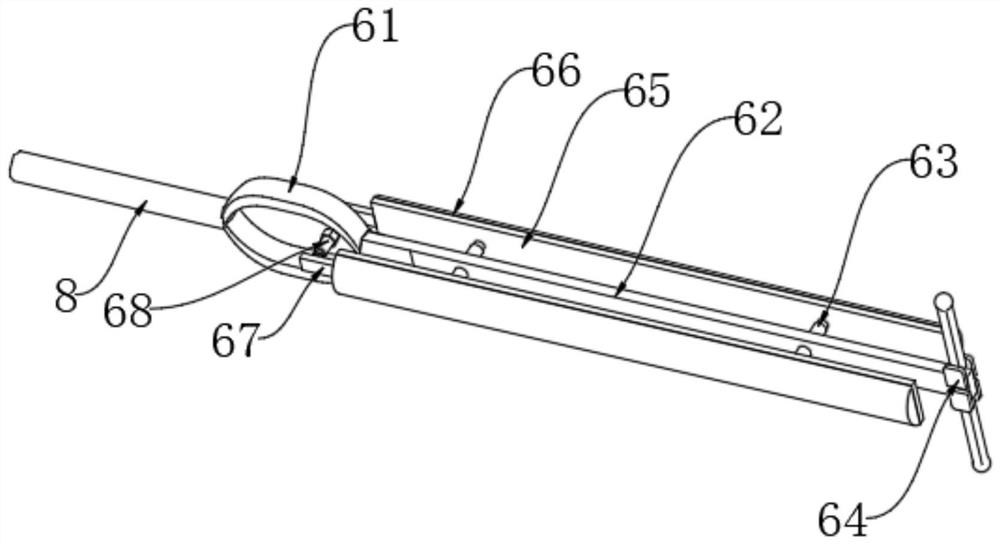
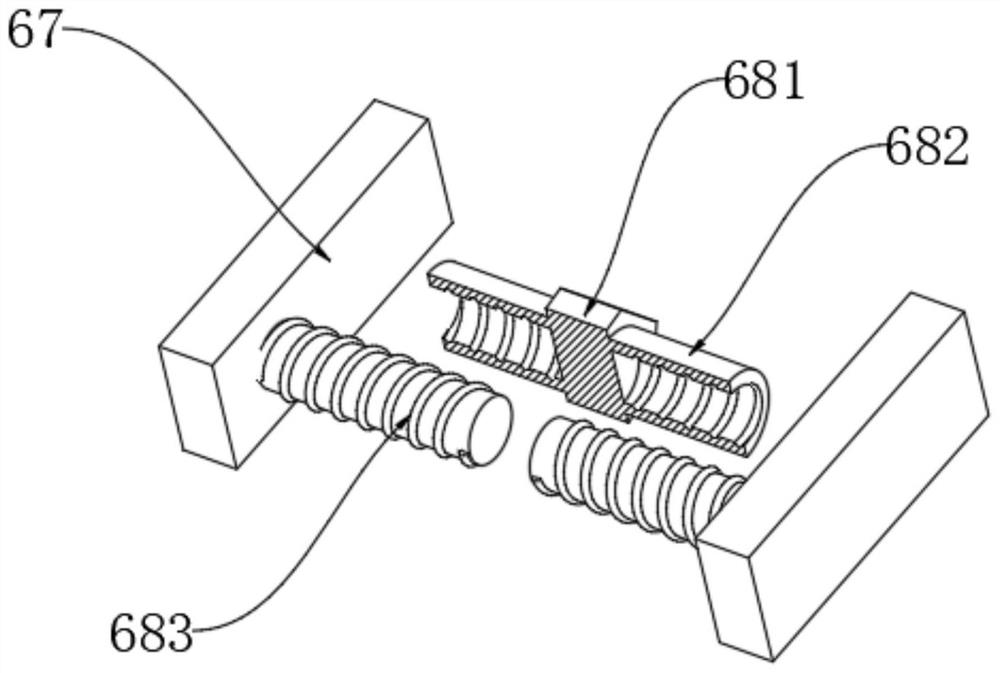
The invention discloses a grinding and polishing clamp for stainless steel part machining and a machining technology of the grinding and polishing clamp. The grinding and polishing clamp comprises a base, a mounting seat is slidably mounted in the middle of the upper end of the base, a lifting supporting column is slidably mounted at the upper end of the mounting seat, and a grinding and polishing assembly is fixedly mounted on the upper portion of the rear end of the lifting supporting column. Two stand columns and a driving motor are fixedly installed on the left portion of the upper end of the base, the upper portions of the opposite faces of the two stand columns are jointly and rotationally connected with a shaft rod, and the right end of the shaft rod penetrates through the stand column located on the right side, extends to the right side of the stand column, and a clamping device is fixedly installed at the right end of the shaft rod. According to the grinding and polishing clamp for stainless steel part machining and the machining technology of the grinding and polishing clamp, the automation degree is high, the working efficiency is high, the utilization rate of a grinding abrasive belt and the overall grinding and polishing quality are improved, and the machining yield is improved to a certain degree; and potential safety hazards caused by the fact that stainless steel pipes are not clamped and fly out in the rotating process due to misoperation can be avoided, and safety is high.

Description

technical field [0001] The invention relates to the technical field of processing equipment for stainless steel parts, in particular to a grinding and polishing fixture for processing stainless steel parts and a processing technology thereof. Background technique [0002] Stainless steel is the abbreviation of stainless acid-resistant steel. It is resistant to air, steam, water and other weak corrosive media and has stainless steel. It is called stainless steel. Grinding is a kind of surface modification technology. Sandpaper with high hardness particles, etc.) to change the physical properties of the material surface through friction, the main purpose is to obtain a specific surface roughness. With the widespread use of stainless steel products in people's lives, people's production requirements for stainless steel are also getting higher and higher. Stainless steel pipe fittings are passivated when they leave the factory, and a dense oxide film is formed on the surface to ...

Claims


Application Information

Patent Timeline
Patent Type & Authority Applications(China)
IPC IPC(8): B24B21/02B24B41/06B24B21/18B24B41/02B24B47/04B24B41/00
CPCB24B21/02B24B21/18B24B41/007B24B41/02B24B41/067B24B47/04
Inventor 陈嘉祥陈永健陈雪莹
Owner 江门市弈创科技有限公司
Why Eureka
Try Eureka