A dynamic target detection method based on ultra-wideband

A detection method and dynamic target technology, applied in the field of target detection, can solve problems such as small detection range, poor visibility, and difficulty in implementation, and achieve the effects of stable detection threshold, reduced false alarm rate, and improved measurement accuracy

Active Publication Date: 2022-08-09
NANJING UNIV OF SCI & TECH
View PDF5 Cites 0 Cited by
  • Summary
  • Abstract
  • Description
  • Claims
  • Application Information

AI Technical Summary

Problems solved by technology

Infrared detection usually uses infrared equipment such as infrared cameras to obtain the image information of the target area, and then realizes the recognition of the target through image analysis methods, but this detection method requires certain visibility requirements, and it is difficult to implement under poor visibility conditions
Laser detection realizes the detection and speed measurement of the target by emitting laser light to the target and receiving the reflected light, but this method is difficult to implement in the case of many obstacles; ultrasonic detection uses the reflected wave of the ultrasonic wave after the target to realize the target detection. However, due to the severe attenuation of sound waves in the air, this method consumes a lot of power and has a small detection range; radio detection uses the properties of reflection, diffraction, and penetration of radio waves with different center frequencies to detect targets. The radio technologies currently used in target detection include Zigbee, Bluetooth, Wifi, etc. These technologies have the characteristics of low power consumption, low cost, and portability. However, Zigbee, Bluetooth, and Wifi, as more traditional radio technologies, are all affected by multipath effects. impact, resulting in reduced accuracy in some complex environments

Method used


Image

  • A dynamic target detection method based on ultra-wideband
  • A dynamic target detection method based on ultra-wideband
  • A dynamic target detection method based on ultra-wideband

Examples


Embodiment Construction

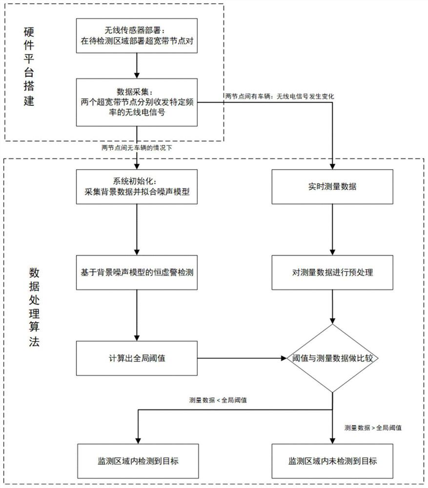
[0035] The present invention will be further introduced below with reference to the accompanying drawings and specific embodiments.

[0036] combine figure 1 , to implement the dynamic target detection method based on ultra-wideband. In this example, the vehicle is used as the dynamic target, and the specific detection includes the following steps:

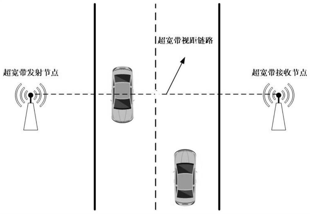
[0037] Step 1. Combine figure 2 , deploy a pair of UWB transmit / receive nodes in the monitoring area, one as the transmitter and the other as the receiver to communicate with each other.

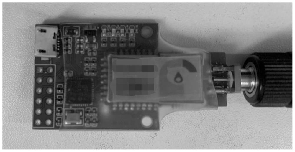
[0038] The ultra-wideband node uses STM32F103T8U6 as the main control chip, and the UWB communication module uses the DW1000 chip of Decawave Company. The two communicate with each other through the SPI protocol, and the main control chip transmits the received RSS data to the host computer through the serial port.

[0039] Step 2: Collect n groups of background RSS data in the absence of vehicles, and perform noise model fitting on the data....


PUM


Abstract

The invention discloses a method for dynamic target detection with ultra-wideband technology. The method first needs to deploy a pair of UWB nodes on both sides of the area to be detected as sensors, and they send and receive UWB signals of specific frequencies to each other as acquisition signals. After the sensor is deployed, preliminary background collection and noise model fitting are required first. This process is performed only once and can be regarded as system initialization. Based on the obtained noise model, we use constant false alarm detection and a series of specific methods proposed for the difficulty of this problem to calculate the target detection threshold, thereby realizing real-time detection of dynamic targets. The experimental results show that the detection results obtained in this method greatly reduce the influence of clutter on the detection accuracy, and obtain a lower false alarm rate and a higher detection rate. With the development of wireless sensor networks, the present invention can be networked and deployed in sensitive areas, and has broad application prospects in the fields of battlefield monitoring, intelligent transportation and the like.

Description

technical field [0001] The invention belongs to the field of target detection, in particular to an ultra-wideband-based dynamic target detection method. Background technique [0002] The invention aims to realize the non-contact existence detection of the target in a certain area, and can be used in the fields of interval speed measurement, target identification and tracking, target positioning, battlefield monitoring and the like. Existing commonly used non-contact target detection technologies include infrared detection, laser detection, ultrasonic detection and radio detection. Infrared detection usually uses infrared equipment such as infrared cameras to obtain image information of the target area, and then realizes the recognition of the target through image analysis methods. However, this detection method requires certain visibility requirements and is difficult to implement under the condition of poor visibility. Laser detection realizes the detection and speed measu...

Claims


Application Information

Patent Timeline
Patent Type & Authority Patents(China)
IPC IPC(8): G01S5/02
CPCG01S5/02Y02D30/70
Inventor 王满意杨佳星陈龙淼徐亚栋王佳乐赵宇轩
Owner NANJING UNIV OF SCI & TECH
Why Eureka
Try Eureka