Differentiated array beam wavefront corrector preparation method based on aberration measurement

A technology of wavefront correctors and array beams, applied in optics, instruments, optical components, etc., can solve the problems of lack of design flexibility and no design of aberration characteristics of incident beams

Active Publication Date: 2021-08-27
NAT UNIV OF DEFENSE TECH
View PDF15 Cites 5 Cited by
  • Summary
  • Abstract
  • Description
  • Claims
  • Application Information

AI Technical Summary

Problems solved by technology

There is no report on the application of such deformable mirrors for wavefront correction of arrayed beams
[0012]Shortcomings or deficiencies of the current technology: the arrangement of the driver electrodes in each cell is consistent, the wavefront aberration correction capability is the same, and there is no aberration of the incident beam corresponding to each cell Features targeted design, lack of design flexi

Method used


Image

  • Differentiated array beam wavefront corrector preparation method based on aberration measurement
  • Differentiated array beam wavefront corrector preparation method based on aberration measurement
  • Differentiated array beam wavefront corrector preparation method based on aberration measurement

Examples


Embodiment 1

[0071] Glossary:

[0072] Corrector: It can produce surface shape changes according to the control signal, which is used to correct the wavefront phase distortion of the beam incident on its surface. Divided into tilting mirrors for correcting global oblique aberrations and deformable mirrors for correcting higher-order aberrations.

[0073] Deformable Mirror: A type of corrector used to correct higher order aberrations.

[0074] Driver: The active unit that performs deformation in the corrector, usually composed of piezoelectric ceramics, magnetostrictive materials, etc.

[0075] Electrode: A metal element that is connected to the driver and applies a voltage to the driver, usually in the form of a copper sheet or other metal mask.

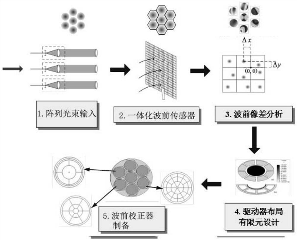
[0076] Such as image 3 As shown, the preparation method of the differential array beam wavefront corrector based on aberration measurement of the present invention, the N-way array beam is incident on the differential array beam wavefront cor...


PUM


Abstract

The invention discloses a differential array beam wavefront corrector preparation method based on aberration measurement. The method comprises the following steps of measuring the distortion wavefront deviation of each sub-beam in an array beam comprising a plurality of sub-beams, and carrying out the three-dimensional modeling of an integrated wavefront corrector through three-dimensional modeling software, importing the model into simulation software for simulation optimization, judging whether the deformation amount and the resonant frequency of each sub-beam deformable mirror of the corrector meet design requirements or not, and if so, recording mirror body structure parameters, otherwise, conducting three-dimensional modeling again, and continuing simulation optimization until the design requirement is met, and preparing the differential wavefront corrector according to the structural parameters of the mirror body. The method has the advantages of low cost, compact system structure, customized design, high correction efficiency and the like.

Description

technical field [0001] The invention relates to the fields of incoherent array laser synthesis and adaptive optics, in particular to a method for preparing a differential array beam wavefront corrector based on single-beam aberration measurement. Background technique [0002] Traditional high-energy laser systems generally use a single high-power laser as the laser light source, which has complex thermal management, poor beam quality, and poor mobility. At present, the array synthesis of the beams emitted by multiple low-power lasers is one of the effective ways to achieve high-power laser output. [0003] Array beam synthesis refers to arranging multiple single beams according to a certain spatial position to form an array beam and then synthesize and output it. Array beam combining can be divided into coherent combining and non-coherent combining. [0004] According to the basic principles of physical optics, to achieve stable interference, the frequency and polarization...

Claims


Application Information

Patent Timeline
IPC IPC(8): G02B27/00
CPCG02B27/0025G02B27/0012G02B2207/125
Inventor 宁禹何宇龙孙全习峰杰许晓军
Owner NAT UNIV OF DEFENSE TECH
Why Eureka
Try Eureka