Incinerator flue gas purification treatment system and purification treatment method

A flue gas purification and treatment system technology, which is applied in the field of flue gas purification, can solve the problems of reducing the contact area of ​​flue gas and smoke dust, reducing the treatment effect of purification equipment, and reducing the adsorption efficiency of activated carbon, so as to enhance the purification effect and simplify manual operation. Steps to ensure the effect of adsorption efficiency

Inactive Publication Date: 2021-08-31
湖北森态香精香料有限公司
View PDF0 Cites 2 Cited by
  • Summary
  • Abstract
  • Description
  • Claims
  • Application Information

AI Technical Summary

Problems solved by technology

[0005] The present invention can solve the problem that when the dust in the flue gas of the incinerator is processed, the dust is usually adsorbed on the purification equipment by means of adsorption, which will reduce the treatment effect of the purification equipment, and because the flue gas purification treatment is usually in a sealed space, Therefore, it is difficult to clean and collect the adsorbed smoke and dust, and when using activated carbon to purify the flue gas of the incinerator, the flue gas is usually passed through the activated carbon pile directly, and the accumulation of activated carbon will reduce the contact area with the flue gas and smoke, Thereby reducing the adsorption efficiency of activated carbon, thereby reducing the purification effect of flue gas

Method used


Image

  • Incinerator flue gas purification treatment system and purification treatment method
  • Incinerator flue gas purification treatment system and purification treatment method
  • Incinerator flue gas purification treatment system and purification treatment method

Examples


Embodiment Construction

[0036] The embodiments of the present invention will be described in detail below with reference to the accompanying drawings, but the present invention can be implemented in many different ways defined and covered by the claims.

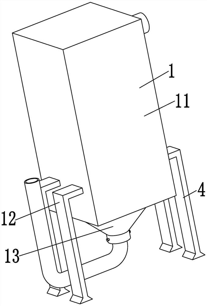
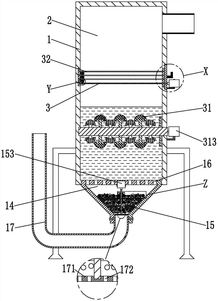
[0037] Such as Figure 1 to Figure 8As shown, an incinerator flue gas purification treatment system includes a reaction tower 1, a working chamber 2 and a purification device 3. The inside of the reaction tower 1 is provided with a working chamber 2, and the working chamber 2 is provided with a purification device 3; The lower side of the working chamber 2 is equipped with a chemical solution, which can treat the smoke in the flue gas.

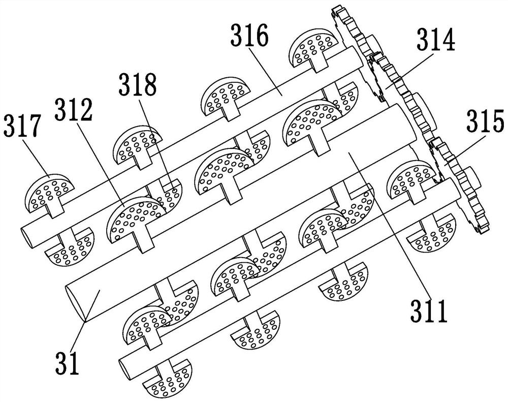
[0038] The reaction tower 1 includes a working tower 11, a support rod group 12, an installation frame 13, a cavity 14, an adsorption mechanism 15, an automatic exhaust valve 16 and a feed pipe 17, and the lower sides of the left and right side walls of the working tower 11 are symmetrical A support rod group 4 is ...


PUM


Abstract

The invention relates to an incinerator flue gas purification treatment system and a purification treatment method.The incinerator flue gas purification treatment system comprises a reaction tower, a working cavity and a purification device, the working cavity is formed in the reaction tower, and the purification device is arranged in the working cavity. The invention can solve the technical problems that when smoke dust in smoke of an incinerator is treated, the smoke dust is usually adsorbed to purification equipment in an adsorption mode, the treatment effect of the purification equipment can be reduced, and the adsorbed smoke dust is difficult to clean and collect due to the fact that smoke purification treatment is usually carried out in a sealed space; besides, when the flue gas of the incinerator is purified by using activated carbon, the flue gas generally directly passes through an activated carbon pile, and the activated carbon is stacked together to reduce the contact area with the flue gas and smoke dust, so that the adsorption efficiency of the activated carbon is reduced, and the purification effect of the flue gas.

Description

technical field [0001] The invention relates to the technical field of flue gas purification, in particular to an incinerator flue gas purification treatment system and a purification treatment method. Background technique [0002] The incinerator is a kind of harmless treatment equipment commonly used in the harmless treatment of medical and domestic waste and animals. Its principle is to use coal, fuel oil, gas and other fuels to incinerate and carbonize the objects to be treated at high temperature to achieve the purpose of disinfection. During the working process of the incinerator, a large amount of flue gas will be produced, which is a mixture of gas and soot. The gas includes sulfur dioxide, nitrogen, oxygen, carbon monoxide, carbon dioxide, hydrocarbons and nitrogen oxides, etc., and the soot may include fuel. The ash, coal particles, oil droplets and high-temperature cracking products, etc., the flue gas of the incinerator will cause serious pollution to the enviro...

Claims


Application Information

Patent Timeline
Patent Type & Authority Applications(China)
IPC IPC(8): B01D53/06B01D53/78B01D46/12B01D46/00
CPCB01D53/06B01D53/78B01D46/12B01D2258/0283B01D2253/102B01D46/681
Inventor 叶露
Owner 湖北森态香精香料有限公司
Why Eureka
Try Eureka