Pipe corner cutting equipment for furniture production

A technology for pipe and angle cutting, applied in metal processing equipment, other manufacturing equipment/tools, manufacturing tools, etc., can solve problems such as reduced work efficiency, poor air quality, and angle adjustment of pipes that cannot be clamped, so as to facilitate clamping The effect of holding and fixing, increasing friction and firm clamping

Pending Publication Date: 2021-08-31
魏俊玲
View PDF0 Cites 2 Cited by
  • Summary
  • Abstract
  • Description
  • Claims
  • Application Information

AI Technical Summary

Problems solved by technology

[0005] Aiming at the deficiencies of the prior art, the present invention provides a pipe corner cutting equipment for furniture production, which solves the problem that the existing pipe corner cutting equipment for furniture production cannot firmly clamp pipes of different sizes and cannot It is possible to adjust the angle of the clamped pipe, which makes it inconvenient to cut the corner of the pipe according to the needs, and does not have the function of grinding and polishing the corner cutting part of the pipe. After the corner cutting of the pipe is completed, the staff needs to put the pipe Take it off and take it to the grinding equipment for grinding and polishing. The operation process is cumbersome, time-consuming and labor-intensive, which increases the workload of the staff and leads to a decrease in work efficiency. In addition, a large amount of dust and slag will be generated when the pipe is cut. Impurities lead to poor air quality around the working environment, dirty working environment, and affect the health of the staff

Method used


Image

  • Pipe corner cutting equipment for furniture production
  • Pipe corner cutting equipment for furniture production
  • Pipe corner cutting equipment for furniture production

Examples


Embodiment Construction

[0028] The following will clearly and completely describe the technical solutions in the embodiments of the present invention with reference to the accompanying drawings in the embodiments of the present invention. Obviously, the described embodiments are only some, not all, embodiments of the present invention. Based on the embodiments of the present invention, all other embodiments obtained by persons of ordinary skill in the art without making creative efforts belong to the protection scope of the present invention.

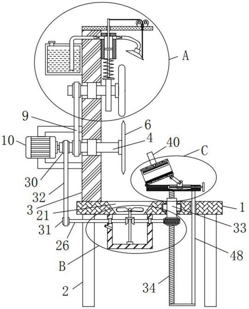
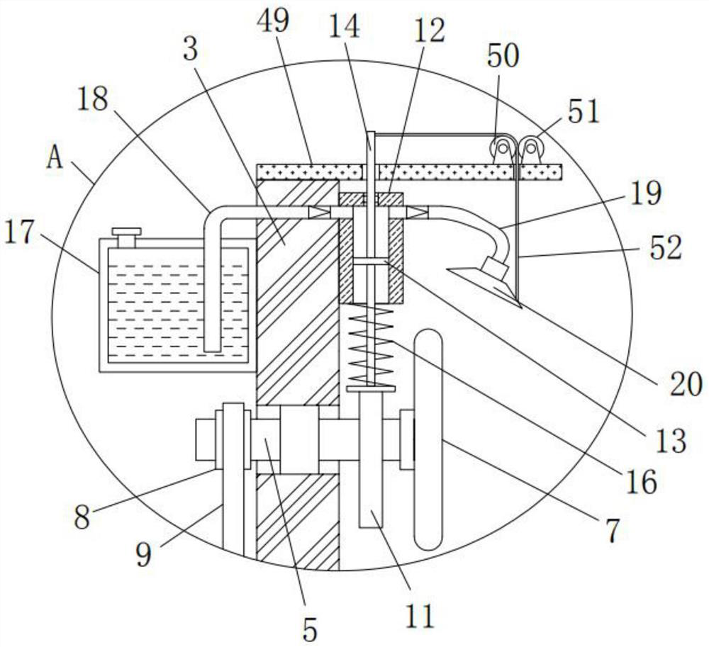
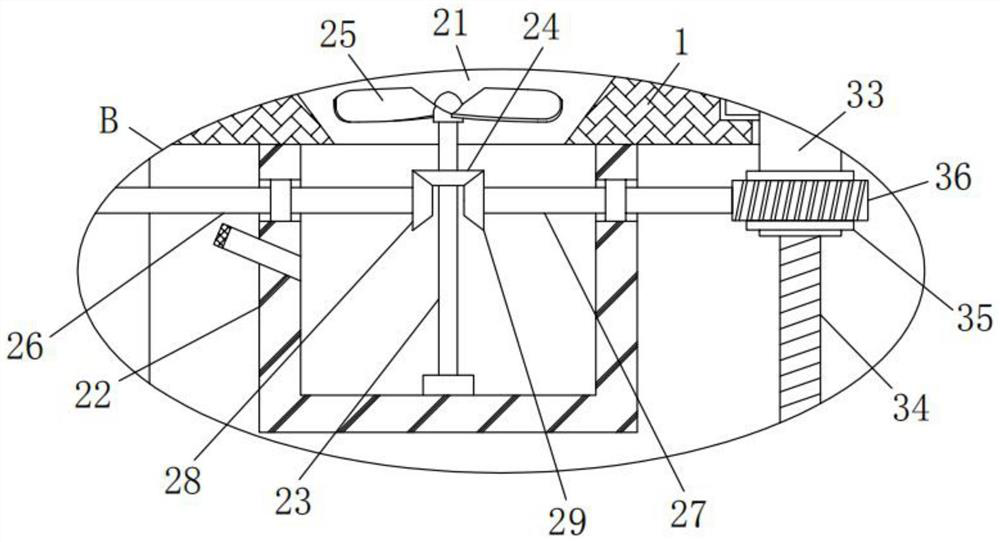
[0029] Such as Figure 1-5 As shown, the present invention provides a technical solution: a pipe corner cutting equipment for furniture production, including a platform 1, four support legs 2 are fixedly installed on the bottom of the platform 1, and the four support legs 2 are symmetrically arranged in pairs. 1 is fixedly installed with a riser 3, and one side of the riser 3 is provided with two first mounting holes, and the first rotating shaft 4 and the sec...


PUM


Abstract

The invention discloses pipe corner cutting equipment for furniture production. The pipe corner cutting equipment comprises a platform, four supporting legs are fixedly installed at the bottom of the platform, the four supporting legs are symmetrically arranged in pairs, a vertical plate is fixedly installed at the top of the platform, and two first mounting holes are formed in one side of the vertical plate. The pipe corner cutting equipment is reasonable in design and good in practicability, pipes with different sizes can be stably clamped, the inclination angle of the pipes can be adjusted, the pipes can be conveniently subjected to corner cutting processing, integrated processing of corner cutting of the pipes and grinding and polishing of cut portions of the pipes can be realized, the working time and the labor amount of workers are saved, the operation steps are reduced, the working efficiency is improved, in the process of corner cutting and grinding and polishing of the pipes, a good dust falling and removing function can be fulfilled, the air quality around the working environment is effectively improved, the working environment is prevented from being sanitary and dirty, and the health of workers cannot be damaged.

Description

technical field [0001] The invention relates to the technical field of pipe angle cutting, in particular to a pipe angle cutting equipment for furniture production. Background technique [0002] Furniture refers to the essential equipment and facilities for human beings to maintain normal life, engage in production practice and carry out social activities. Furniture also follows the pace of the times and continues to develop and innovate. Up to now, there are many categories, different materials, complete varieties, and different uses. , is an important foundation for establishing a working and living space. With the development of the times, there are many types of furniture innovations, and the required materials become diverse and more complex. In the furniture production process, pipes are the most commonly used materials for making furniture. One, the types and sizes of the pipes used may be different, and the pipes required to make different furniture are also quite di...

Claims


Application Information

Patent Timeline
IPC IPC(8): B23P23/04B23Q3/06B23Q1/25B23Q11/10B01D47/06
CPCB01D47/06B23P23/04B23Q1/25B23Q3/064B23Q11/10
Inventor 魏俊玲
Owner 魏俊玲
Why Eureka
Try Eureka