Anti-splashing ceramic tile cutting platform capable of achieving rapid positioning and cutting technology of anti-splashing ceramic tile cutting platform

A cutting platform and anti-splash technology, which is applied in the field of cutting tools, can solve the problems of tile slag splashing, harming staff, affecting cost and quality, and affecting cutting efficiency, so as to increase accuracy and positioning efficiency, improve cutting efficiency, and ensure The effect of accuracy

Pending Publication Date: 2021-08-31
YANGXI BODE PRECISION IND BUILDING MATERIAL CO LTD
View PDF6 Cites 0 Cited by
  • Summary
  • Abstract
  • Description
  • Claims
  • Application Information

AI Technical Summary

Problems solved by technology

[0002] With the development of the mechanical processing industry and the construction industry, the requirements for cutting quality and precision are constantly improving. For ceramic tiles, various types of ceramic tiles have also appeared on the market as people's needs change. Similarly, for tiles of various specifications, the current cutting machine cannot be well adapted to various tiles, especially some tiles with relatively large specifications, which cannot be placed flat on the working platform of the cutting machine, which will naturally affect Cutting quality, work efficiency, and virtually increased costs, the existing cutting machines have greater requirements for cutting precision, but the existing cutting machines can not meet the scientific and accurate positioning, all require the cutter to rely on experience , cut by feeling, or use a ruler to measure first and then cut. This will still have a certain error for ceramic tiles that require high precision. The platform has become an urgent need of the market
[0003] 1. Since the existing tile cutting platform does not have the function of quickly locating the cutting position, the work efficiency is slow
[0004] 2. Since the existing tile cutting platform does not have the function of precise positioning of the cutting position, there are errors in the finished products, which affects the cost and quality
[0005] 3. Since the existing tile cutting platform does not have the function of effectively protecting the splash of cutting slag, there is a potential danger of injury to the staff due to the splash of tile slag

Method used


Image

  • Anti-splashing ceramic tile cutting platform capable of achieving rapid positioning and cutting technology of anti-splashing ceramic tile cutting platform
  • Anti-splashing ceramic tile cutting platform capable of achieving rapid positioning and cutting technology of anti-splashing ceramic tile cutting platform
  • Anti-splashing ceramic tile cutting platform capable of achieving rapid positioning and cutting technology of anti-splashing ceramic tile cutting platform

Examples


Embodiment 1

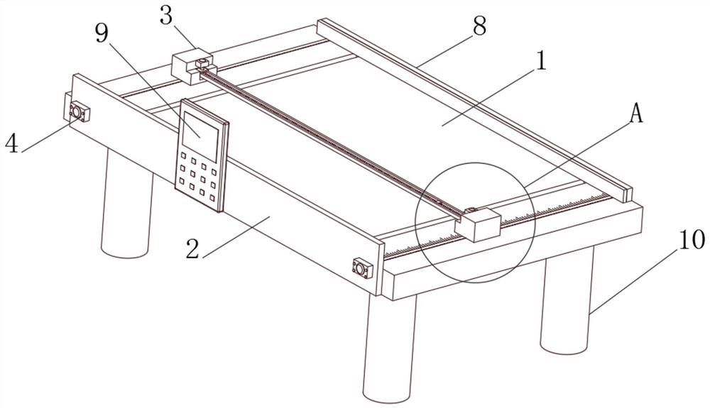
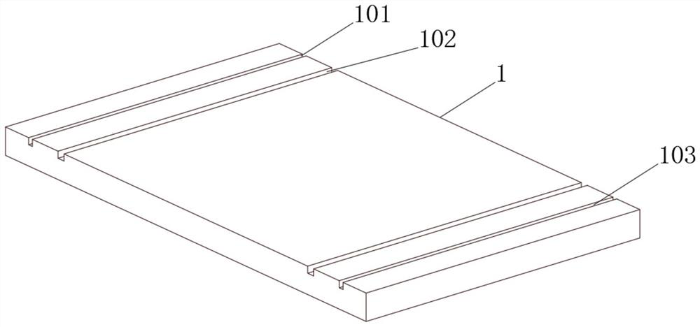
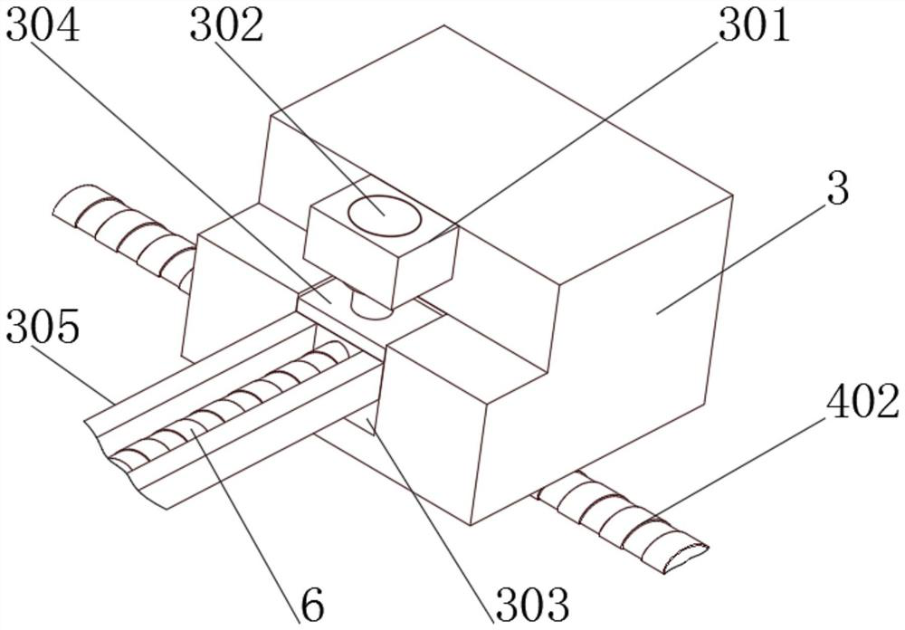
[0039] see Figure 1-5, the present invention provides a technical solution: a quickly positioned anti-splash ceramic tile cutting platform, including a main body 1 and a baffle plate 2, a first chute 101 is opened on the top outer wall of the main body 1, and the inner wall of the first chute 101 slides The first sliding seat 3 is connected, the outer wall of the first sliding seat 3 is fixedly connected with the first installation platform 301, the inner wall of the first installation platform 301 is fixedly connected with the first hydraulic rod 302, and the first hydraulic rod 302 is far away from the first installation platform One end of 301 is fixedly connected with a first slide plate 304, and the outer wall of the first installation platform 301 is provided with a first groove 303, and the inner wall of the first groove 303 is slidingly connected with the outer wall of the first slide plate 304, and one side of the first slide plate 304 The outer wall is fixedly conne...

Embodiment 2

[0042] see Figure 1-6 As shown, on the basis of Embodiment 1, the present invention provides a technical solution: the top outer wall of the main body 1 is provided with a third chute 103, and the inner wall of the third chute 103 is slidably connected with the second sliding seat 5, and the second One side of the outer wall of the slide seat 5 is fixedly connected with a second installation platform 501, and the inner wall of the second installation platform 501 is fixedly connected with a second hydraulic rod 502, and one end of the second hydraulic rod 502 away from the second installation platform 501 is fixedly connected with a second Sliding plate 504, the outer wall of the second mounting platform 501 is provided with a second groove 503, the inner wall of the second groove 503 is slidingly connected with the outer wall of the second sliding plate 504, and the inner wall of the second sliding plate 504 is fixedly connected with the second motor 505. The output shaft of...

Embodiment 3

[0045] see Figure 1-8 As shown, on the basis of Embodiment 1 and Embodiment 2, the present invention provides a kind of technical scheme: the outer wall of the third screw mandrel 6 is threadedly connected with knife seat 7, and the outer walls of both sides of knife seat 7 are all connected with the outer wall of track 305 Sliding connection, the bottom outer wall of the knife seat 7 is fixedly connected with a knife head 701, the outer wall of the main body 1 is provided with a second chute 102, the top outer wall of the main body 1 is provided with a push plate 8, and one side of the outer wall of the push plate 8 is fixedly connected with a rubber Gasket 801, the bottom outer wall of push plate 8 is fixedly connected with slider 802, the outer wall of slider 802 is fixedly connected with the inner wall of second chute 102, the outer wall of push plate 8 and the outer wall of main body 1 pass through the second chute provided 102 and slider 802 are slidably connected.

[...


PUM


Abstract

The invention discloses an anti-splashing ceramic tile cutting platform capable of achieving rapid positioning and a cutting technology of the anti-splashing ceramic tile cutting platform. The anti-splashing ceramic tile cutting platform comprises a main body and a baffle, wherein a first sliding groove is formed in the outer wall of the top of the main body, a first sliding base is slidably connected to the inner wall of the first sliding groove, a first installing table is fixedly connected to the outer wall of the first sliding base, a first hydraulic rod is fixedly connected to the inner wall of the first installing table, a first sliding plate is fixedly connected to the end, away from the first installing table, of the first hydraulic rod, a first groove is formed in the outer wall of the first installing table, the inner wall of the first groove is slidably connected to the outer wall of the first sliding plate, a rail is fixedly connected to the outer wall of one side of the first sliding plate, and a machine base is arranged on the outer wall of the main body. The cutting length is adjusted by controlling the number of turns of rotation of a motor in a numerical control mode, compared with an existing cutting machine, the cutting machine is faster and more accurate, automatic cutting adjustment is achieved, the cutting efficiency is improved, and the position correction accuracy and the positioning efficiency are improved.

Description

technical field [0001] The invention belongs to the technical field of cutting tools, and in particular relates to a rapidly positioned anti-splash ceramic tile cutting platform and a cutting process thereof. Background technique [0002] With the development of the mechanical processing industry and the construction industry, the requirements for cutting quality and precision are constantly improving. For ceramic tiles, various types of ceramic tiles have also appeared on the market as people's needs change. Similarly, for tiles of various specifications, the current cutting machine cannot be well adapted to various tiles, especially some tiles with relatively large specifications, which cannot be placed flat on the working platform of the cutting machine, which will naturally affect Cutting quality, work efficiency, and virtually increased costs, the existing cutting machines have greater requirements for cutting precision, but the existing cutting machines can not meet th...

Claims


Application Information

Patent Timeline
Patent Type & Authority Applications(China)
IPC IPC(8): B28D1/22B28D7/00B28D7/04
CPCB28D1/225B28D7/04B28D7/005B28D7/00
Inventor 杨俊宏俞诗雄博文峰许培同严秀华连传超罗旺金
Owner YANGXI BODE PRECISION IND BUILDING MATERIAL CO LTD
Why Eureka
Try Eureka