Lifting three-wing small wind power generation equipment based on three sets of generators
A technology for wind power generation equipment and generators, which is applied to wind engines, mechanical equipment, wind engines, etc. in the same direction as the wind, to achieve the effects of increasing the scope of application, reducing the difficulty of operation, and improving stability
- Summary
- Abstract
- Description
- Claims
- Application Information
AI Technical Summary
Problems solved by technology
Method used
Image
Examples
Embodiment 1
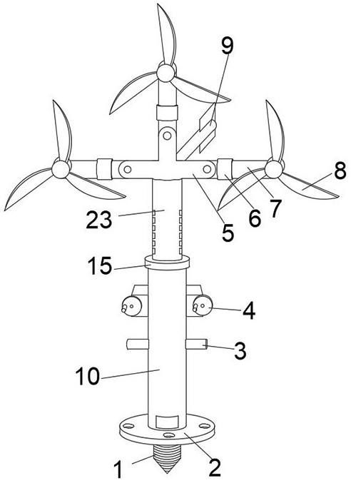
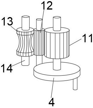
[0036] One end of the drive turntable 4 is provided with a first gear 11, and a second gear 12 is movably installed on the outer surface of the side of the first gear 11. When the user lifts and adjusts the lifting column 23, the user can rotate the drive turntable 4 , so that the drive turntable 4 cooperates with the first gear 11 to drive the second gear 12, through the second gear 12 for speed change adjustment, using the second gear 12 to cooperate with the third gear 13, through the locking tooth structure on the side of the lifting column 23, to drive the lifting column 23 for lifting adjustment, thereby adjusting the use height of the three-wing wind power generation equipment.
[0037] The side outer surface of the second gear 12 is movably equipped with a third gear 13, the middle part of the third gear 13 is an arc structure, and the two ends of the third gear 13 are columnar structures. During the adjustment operation, the position of its arc structure can better fi...
Embodiment 2
[0039] The cross-sectional diameter of the second gear 12 is less than the cross-sectional diameter of the first gear 11, and the middle parts of the first gear 11, the second gear 12 and the third gear 13 are all sleeved with a docking rotating rod 14, and the setting of the connecting rotating rod 14 is utilized , so that the first gear 11, the second gear 12 and the third gear 13 can all be rotated, and at the same time, the setting of the second gear 12 can increase the speed of the lifting column 23 during the lifting operation, and play a role in changing the speed of the lifting column 23. The role of regulation.
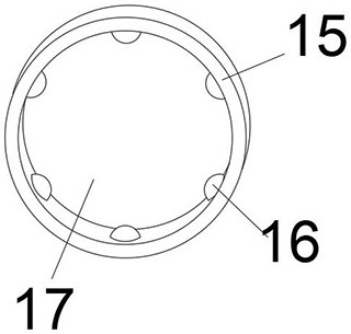
[0040] A lifting snap ring 15 is sleeved between the top of the support column 10 and the lifting column 23, and several groups of rollers 16 are movably installed on the inner side of the lifting snap ring 15. The middle part of the lifting snap ring 15 is provided with a circular through hole 17. The roller 16 inside the clasp 15 can reduce the frictional f...
Embodiment 3
[0042] The middle part of the lower end of the tripod card frame 5 is provided with a swivel deck 18, and the lower part of the side outer surface of the swivel deck 18 is provided with an annular slot 20, and the swivel deck is passed between the tripod rack 5 and the lifting column 23. 18 movable connections, the wind vane 9 is installed at the tail of the three-head card frame 5, and the setting of the rotating card seat 18 and the annular card slot 20 can be used in conjunction with the wind vane 9 to adjust the use direction of the three-wing wind power generation equipment. The outer surface of the lower end of 10 is fixedly installed with a fixed chassis 2, and the outer surfaces of both sides of the support column 10 are provided with lifting slots. The setting of the fixed chassis 2 can cooperate with the use of bolts to reinforce the installation of the support column 10. effect, utilize the lifting card slot simultaneously, can promote the lifting sleeve handle 3, ap...
PUM
 Abstract
Description
Claims
Application Information
 - R&D
- Intellectual Property
- Life Sciences
- Materials
- Tech Scout
- Unparalleled Data Quality
- Higher Quality Content
- 60% Fewer Hallucinations
Browse by: Latest US Patents, China's latest patents, Technical Efficacy Thesaurus, Application Domain, Technology Topic, Popular Technical Reports.
© 2025 PatSnap. All rights reserved.Legal|Privacy policy|Modern Slavery Act Transparency Statement|Sitemap|About US| Contact US: help@patsnap.com


