
Low-profile broadband wide-angle scanning tight coupling antenna unit and array

A technology of wide-angle scanning and antenna unit, which is applied in the direction of antenna array, antenna, antenna grounding device, etc., to achieve the effect of improving the matching effect, improving the matching performance, and increasing the sweep angle range

Pending Publication Date: 2021-08-31
SOUTHEAST UNIV +1
View PDF0 Cites 2 Cited by
  • Summary
  • Abstract
  • Description
  • Claims
  • Application Information

AI Technical Summary

Problems solved by technology

[0003] The purpose of the present invention is to provide a low-profile, ultra-broadband and wide-sweep angle antenna array element and tightly coupled antenna array to overcome the problems of active standing wave bandwidth and profile height of existing phased array antenna arrays

Method used


Image

  • Low-profile broadband wide-angle scanning tight coupling antenna unit and array
  • Low-profile broadband wide-angle scanning tight coupling antenna unit and array
  • Low-profile broadband wide-angle scanning tight coupling antenna unit and array

Examples


Embodiment Construction

[0025] Embodiments of the technical solutions of the present invention will be described in detail below in conjunction with the accompanying drawings. The following examples are only used to illustrate the technical solutions of the present invention more clearly, and therefore are only examples, rather than limiting the protection scope of the present invention.

[0026] It should be noted that, unless otherwise specified, the technical terms or scientific terms used in this application shall have the usual meanings understood by those skilled in the art to which the present invention belongs.

[0027] In the description of the present application, it is to be understood that the terms "horizontal", "vertical", "upper", "lower", "front", "back", "X axis", "Y axis" etc. indicate orientation Or the positional relationship is based on the orientation or positional relationship shown in the drawings, which is only for the convenience of describing the present invention and simpl...


PUM


Abstract

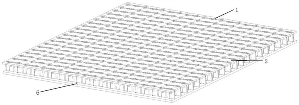
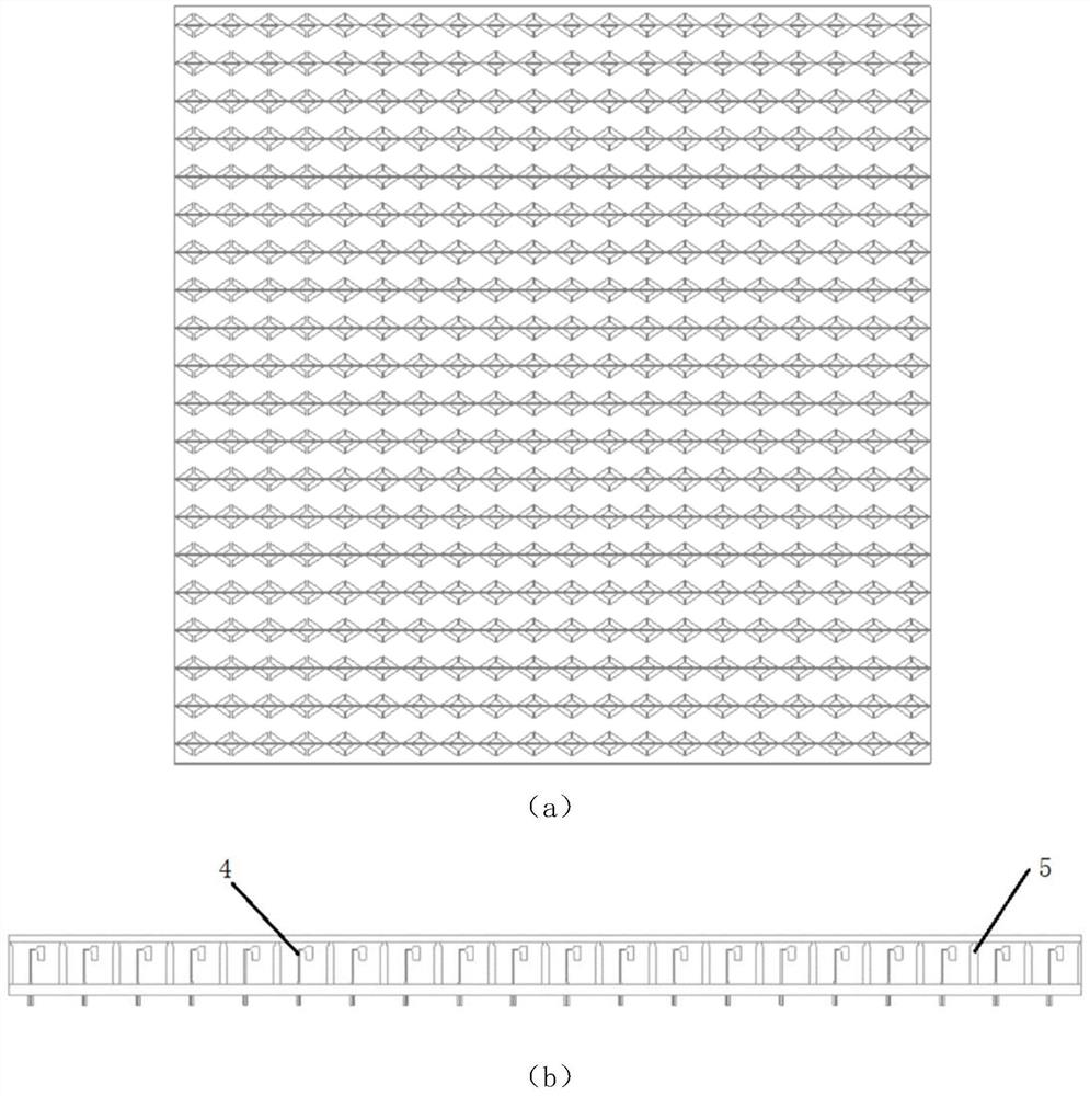
The invention discloses a low-profile broadband wide-angle scanning tight coupling antenna unit and array. The antenna unit comprises a V-shaped split ring, a medium matching layer, an antenna radiation patch , an ultra-wideband balun and a reflection floor, wherein the V-shaped split ring is formed by enclosing two subunits, and the two subunits are spaced to form an opening; the medium matching layer is positioned below the split ring and is used for arranging the split ring; the antenna radiation patch comprises a first radiation arm and a second radiation arm, and the upper ends of the first radiation arm and the second radiation arm are electrically connected with the two subunits; the ultra-wideband balun comprises a signal input end and an ultra-wideband balun coupling end; the coupling end of the ultra-wideband balun is electrically connected with the lower ends of the first radiation arm and the second radiation arm; and the reflection floor is arranged below the dielectric substrate. According to the tightly coupled antenna designed by the invention, by loading the V-shaped split ring and the dielectric matching layer structure, E-plane + / -60-degree beam scanning can be realized within a frequency band of 6-18 GHz, and meanwhile, the profile height is only 0.069 lambdal.

Description

technical field [0001] The invention relates to the technical field of ultra-wideband antennas, in particular to a low profile wide bandwidth angular scanning tightly coupled antenna unit and array. Background technique [0002] The traditional UWB antenna array design mainly starts with the design of the broadband antenna elements. When considering the array of antenna elements, it is necessary to minimize the mutual coupling effect between the antenna elements to ensure that the impedance matching of the antenna is not deteriorated. Although the traditional array antenna design tends to be mature, it is restricted by the electrical performance of the antenna elements and the array coupling effect, which greatly limits the expansion of the impedance bandwidth and phase-sweep angle of the array antenna. Based on the excitation of wheeler using infinite continuous current elements to construct phased arrays, Ben A.Munk et al proposed a strong coupling ultra-wideband phased ar...

Claims


Application Information

Patent Timeline
IPC IPC(8): H01Q1/38H01Q1/48H01Q21/00
CPCH01Q21/00H01Q1/48H01Q1/38
Inventor 曹振新徐子豪全鑫许湘剑
Owner SOUTHEAST UNIV
Learn More