
Automatic pre-pressing machine for spring production

A pre-press, automatic technology, applied in the direction of manufacturing springs, applications, household appliances, etc. by wire, can solve the problems of inconvenient adjustment of the feeding speed and rotation speed, high noise of the vibrating plate, influence of the processing environment, etc., to achieve convenient disassembly and The effect of cleaning, reducing the occupied space and convenient operation

Inactive Publication Date: 2021-09-03
卓越五金弹簧(深圳)有限公司
View PDF0 Cites 1 Cited by
  • Summary
  • Abstract
  • Description
  • Claims
  • Application Information

AI Technical Summary

Problems solved by technology

[0003] After the spring is produced, it usually needs to be pre-pressed by a pre-pressing machine, and the existing automatic pre-pressing machine is usually a simple disc rotation mechanism to assist hydraulic pressure or mechanical pressing of the rod body. This structure is less efficient for processing, and The structure is usually operated by vibrating plate feeding. It is inconvenient to adjust the feeding speed and the rotating speed of the disc, and the noise generated by the vibrating plate is relatively large, which has a great impact on the processing environment and is troublesome to operate. The existing discharge method usually presses the structure and the discharge structure, occupies a large area and has a relatively loose structure

Method used


Image

  • Automatic pre-pressing machine for spring production
  • Automatic pre-pressing machine for spring production
  • Automatic pre-pressing machine for spring production

Examples


Embodiment Construction

[0036] The following will clearly and completely describe the technical solutions in the embodiments of the present invention with reference to the accompanying drawings in the embodiments of the present invention. Obviously, the described embodiments are only some, not all, embodiments of the present invention. Based on the embodiments of the present invention, all other embodiments obtained by persons of ordinary skill in the art without making creative efforts belong to the protection scope of the present invention.

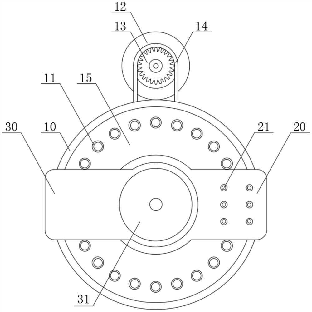
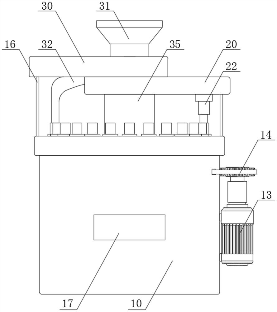
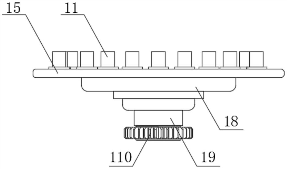
[0037] see Figure 1-6 , the present invention provides a technical solution: an automatic pre-pressing machine for spring production, comprising:

[0038] The base 10, the base 10 is an overall external protection structure, which provides overall support and stability,

[0039] The upper part of the side wall inside the base 10 is welded with a connecting ring 101, the middle part of the base 10 is provided with a support column 102, and the inside of the b...


PUM


Abstract

The invention discloses an automatic pre-pressing machine for spring production. The automatic pre-pressing machine comprises: a base, wherein a connecting ring is welded to the upper portion of the inner side wall of the base, a supporting column is arranged in the middle of the inner portion of the base, a discharging groove is further formed in the position, close to the front wall, of the inner portion of the base, a discharging port is formed in the front surface of the base, a stepping motor is further arranged on one side of the base, and a gear is welded to the power output end of the motor; and a rotating plate, arranged on the upper surface of the base, wherein a plurality of spring sleeves are arranged on the surface of the rotating plate. Through an arranged second connecting plate and an auxiliary structure matched with the second connecting plate, a material plate can be driven to vibrate through vibration of a telescopic motor, a vibration feeding structure is formed, the feeding angle of materials can be guaranteed through a feeding hole formed in the bottom of a feeding groove, and therefore, an entering spring can move along the arc-shaped structure of the material plate and finally directly falls into the spring sleeve.

Description

technical field [0001] The invention relates to the field of spring production, in particular to an automatic pre-pressing machine for spring production. Background technique [0002] A spring is a mechanical part that uses elasticity to work. Parts made of elastic materials are deformed under the action of external force, and return to their original shape after the external force is removed. Generally made of spring steel. [0003] After the spring is produced, it usually needs to be pre-pressed by a pre-pressing machine, and the existing automatic pre-pressing machine is usually a simple disc rotation mechanism to assist hydraulic pressure or mechanical pressing of the rod body. This structure is less efficient for processing, and The structure is usually operated by vibrating plate feeding. It is inconvenient to adjust the feeding speed and the rotating speed of the disc, and the noise generated by the vibrating plate is relatively large, which has a great impact on th...

Claims


Application Information

Patent Timeline
Patent Type & Authority Applications(China)
IPC IPC(8): B21F35/00
CPCB21F35/00
Inventor 蒋晨
Owner 卓越五金弹簧(深圳)有限公司
Learn More