
Drainage plate shearing device, control system and plate shearing process

A technology of a shearing device and a control system, which is applied in the field of inserting machine design, can solve the problems of long cycle of automatic shearing, scratches of workers' cutting tools, harsh operating environment, etc.

Pending Publication Date: 2021-09-03
NAT ENG RES CENT OF DREDGING TECH & EQUIP
View PDF9 Cites 0 Cited by
  • Summary
  • Abstract
  • Description
  • Claims
  • Application Information

AI Technical Summary

Problems solved by technology

In the past, due to the high cost of installing the automatic shearing device, the long period of automatic shearing, and the fact that the automatic shearing was not cut, the installation of automatic shearing devices in commonly used drainage board insertion machines has not been promoted.
[0003] With the development of society, labor costs have increased accordingly, and people have higher and higher requirements for construction safety and environmental conditions. The existing cutting machine drainage boards generally use manual cutting, and workers use sickles or other cutting tools in the process of cutting drainage boards. Low cutting efficiency of double drainage boards, uneven cutting surface, different lengths of drainage boards on the ground, workers are easily scratched by cutting tools, poor operating environment, etc.
However, if double intubation tubes are used to insert the drainage board, two workers are required to cut the drainage board, the labor cost is high, and the shearing efficiency is low, and there is a potential safety hazard for the shearing board
[0004] The above-mentioned shortcomings in the process of cutting the drainage board by the slotting machine have seriously affected the stable, efficient and safe cutting of the drainage board, so there is an urgent need for a new type of drainage board shearing device with a high degree of automation in the market

Method used

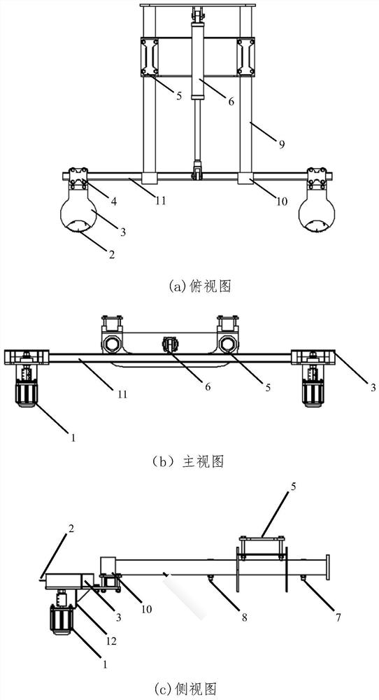
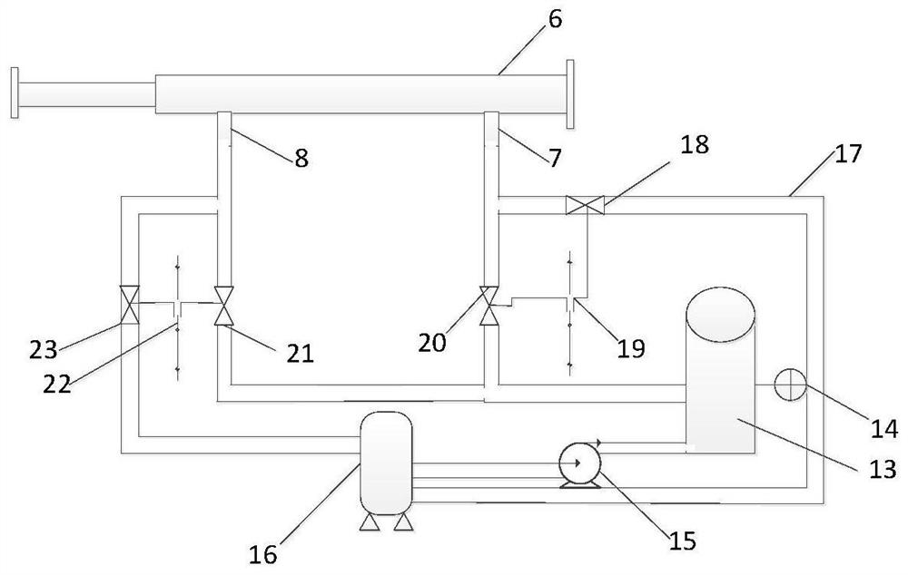
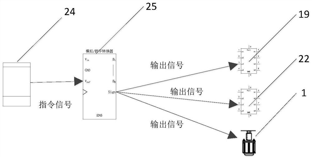

Image

  • Drainage plate shearing device, control system and plate shearing process
  • Drainage plate shearing device, control system and plate shearing process
  • Drainage plate shearing device, control system and plate shearing process

Examples


Embodiment Construction

[0033] The technical solution of the present invention will be further described in detail with specific embodiments below in conjunction with the accompanying drawings. It should be understood that the following examples are only used to illustrate the present invention but not to limit the scope of the present invention.

[0034] A drainage board shearing device, characterized in that:

[0035] figure 1 As shown, it includes components such as a cutting device, a hydraulic push rod telescopic device 6, a support, and the like. The cutting device is extended with the push rod of the hydraulic push rod telescopic device 6, and is used for cutting the drainage board. The bracket is used to provide a bracket for the cutting device and the hydraulic push rod telescopic device 6, and provide a sliding track for the cutting device to advance and retreat toward the intubation direction.

[0036] During specific implementation, the cutting device includes components such as a circ...


PUM


Abstract

The invention discloses a drainage plate shearing device, a control system and a plate shearing process. The drainage plate shearing device mainly comprises a cutting device, a hydraulic push rod telescopic device, a guide rail, a shaft sleeve, a fixed support, a cross beam, the drainage plate shearing device control system and the plate shearing process. According to the drainage plate shearing device control system, automatic plate shearing or key manual plate shearing is carried out, the hydraulic push rod telescopic device completes stretching or retracting operation, plate shearing or rod retracting operation of the drainage plate shearing device is achieved, and the drainage plate shearing work of a plate inserting machine is finally achieved according to the drainage plate shearing process. The devices of the device are detachable, so that the device is convenient to transport and install. By means of the novel drainage plate shearing device, the cutting efficiency and cutting quality of a drainage plate effectively improved, and the labor cost is saved.

Description

technical field [0001] The invention belongs to the technical field of slot machine design. Background technique [0002] With the acceleration of urban construction in our country, the construction of soft soil foundation engineering has developed rapidly. Inserting drainage boards in soft soil foundations is a method to increase soil drainage channels, accelerate the drainage speed of soft soil or silt soil, and greatly reduce the consolidation and settlement time of soft soil foundations. Previously, due to the high cost of installing the automatic shearing device, the long period of automatic shearing, and the fact that the automatic shearing was not cut, the installation of automatic shearing devices on commonly used drainage board insertion machines has not been promoted. [0003] With the development of society, labor costs have increased accordingly, and people have higher and higher requirements for construction safety and environmental conditions. The existing cut...

Claims


Application Information

Patent Timeline
IPC IPC(8): B23D47/00B23D47/02B23D45/10B23Q1/00B23Q15/007B23Q15/013B23Q11/06
CPCB23D47/00B23D47/02B23D45/105B23Q1/0009B23Q15/007B23Q15/013B23Q11/06
Inventor 孙文博冯波袁超哲陶润礼宋伟浩王晓光郝宇驰罗章朱平施绍刚孙旭石煜姜天际卢李俊
Owner NAT ENG RES CENT OF DREDGING TECH & EQUIP
Learn More