Photoelectric sampling device, meter and photoelectric sampling method

A photoelectric sampling and light source technology, applied in the direction of measuring devices, testing/calibrating devices, volume indication and recording equipment, etc., can solve the problems of meter installation, wiring difficulty, no consideration of optical receiver, unfavorable measurement and detection, etc. Achieve the effects of reducing magnetic interference problems, reducing costs, and saving light sources

Pending Publication Date: 2021-09-03
ZHEJIANG WEIXING INTELLIGENT METER STOCK
View PDF1 Cites 0 Cited by
  • Summary
  • Abstract
  • Description
  • Claims
  • Application Information

AI Technical Summary

Problems solved by technology

[0006] However, the light environment using this scheme is not closed, and the problem of ambient light interference in the optical receiver is not considered. The method of photoelectric sampling is to confirm the number of rotations of the turntable through the first signal and the second signal output by the receiver. In this way, it is necessary to know the starting point accurately, which is not conducive to measurement and detection
And for the case where the main control board of the gas meter is removed, the abnormality cannot be detected
If the optical receiver and the optical transmitter are set oppositely, the optical transmitter and the optical receiver need to be equipped with peripheral devices separately, for example, two circuit boards need to be configured or connected through separate power signal lines, so that the installation and operation of the entire meter Lines bring difficulty, maintenance remains unchanged, and cost increases accordingly

Method used


Image

  • Photoelectric sampling device, meter and photoelectric sampling method
  • Photoelectric sampling device, meter and photoelectric sampling method
  • Photoelectric sampling device, meter and photoelectric sampling method

Examples


Embodiment Construction

[0046] In order to facilitate those skilled in the art to better understand the present invention, the present invention will be described in further detail below in conjunction with the accompanying drawings and specific embodiments. The following is only exemplary and does not limit the protection scope of the present invention.

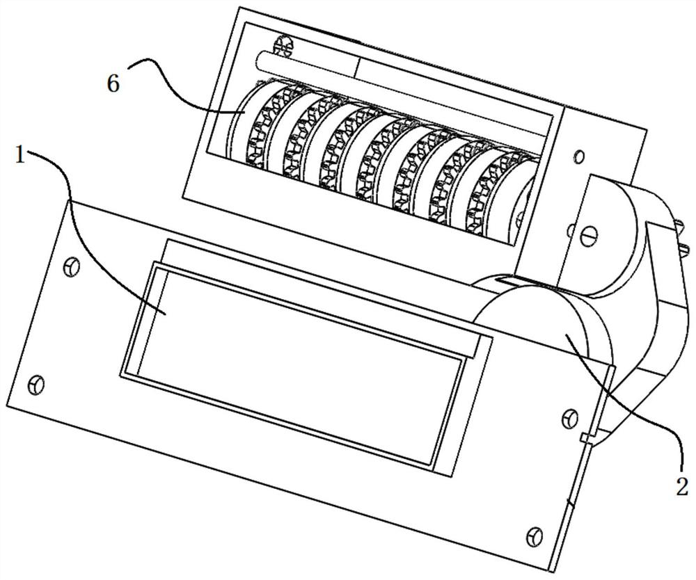
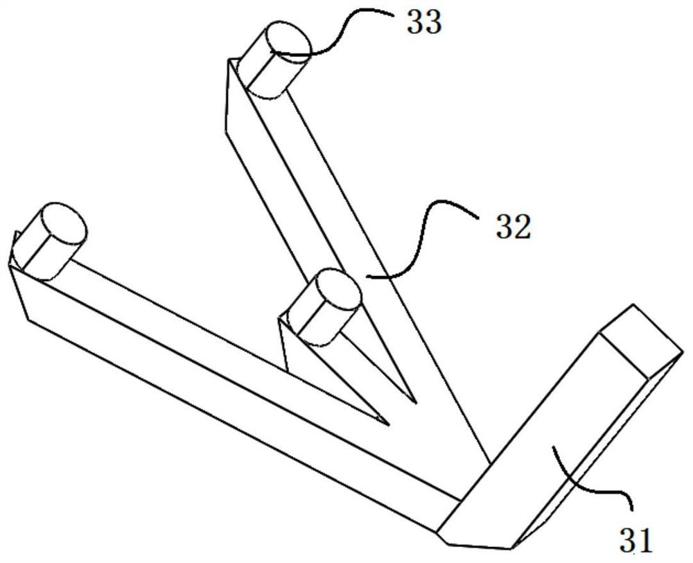
[0047] Such as figure 1 As shown, it is a structural schematic diagram of an embodiment of the practical photoelectric sampling device, including such as figure 2 The shown light guide 3 includes a first light guide part 31, one end of the first light guide part 31 is provided with a light incident surface, and the other end is coupled to the proximal end of the second light guide part 32, and the second light guide part 32 The far end of the ray is bifurcated into several branches, and a light guide post 33 is provided at the end of each branch. The free end face of the light guide post 33 is the light exit surface, and the light exit surface and...


PUM


Abstract

The invention discloses a photoelectric sampling device, a meter and a photoelectric sampling method. The photoelectric sampling device comprises a light guide part, wherein the light guide part comprises a light guide-in part provided with a light inlet face and a plurality of branched light guide-out parts, the light guide-out parts are provided with light outlet faces, and the light outlet faces and the light inlet face are located on the same side of the light guide part; a light emitter which is used for emitting a light source to the light incident surface; a light receiver which is used for collecting light signals of the light emergent surface; a shading part which is arranged between the light guide part and the light receiver and provided with a shading area and a light transmitting area which correspond to the light emergent surface, wherein when the shading part rotates around the shading part, the light transmitting area and the shading area are driven to alternately pass through the light emergent surface; and a meter which comprises a photoelectric sampling device, wherein a base meter gear of the photoelectric sampling device drives a shading part to rotate around the base meter gear. The photoelectric sampling method is used for collecting the signals of the light emitting surface based on a preset period, and determining the number of turns of rotation of the basic meter character wheel based on the collected coding value. Light incoming and light outgoing are arranged on the same side, assembly is simple, reliability is high, and cost is reduced.

Description

technical field [0001] The invention relates to the field of intelligent meter measurement, in particular to a photoelectric sampling device, a meter and a photoelectric sampling method. Background technique [0002] With the popularization of smart gas meters, higher requirements are put forward for the accuracy of smart gas meter readings and the performance of gas meters. The existing smart membrane gas needs to obtain the reading value of the base meter counter, where the roller of the base meter counter The adding operation is performed according to the gas volume used, every time a unit volume is used, the count of the roller is increased by one, so as to realize the measurement of the gas volume. There are generally three ways to read the counter of the base meter: Hall to get the letter, reed switch to get the letter or photoelectric direct reading counter to get the letter. [0003] Among them, both Hall receiver and reed switch need to install a magnet on the coun...

Claims


Application Information

Patent Timeline
Patent Type & Authority Applications(China)
IPC IPC(8): G01F1/56G01F1/66G01F15/06G01F25/00
CPCG01F1/661G01F1/662G01F1/56G01F15/06
Inventor 邹航汉业朗龚一帆张燕斌刘青赵彦华王兵
Owner ZHEJIANG WEIXING INTELLIGENT METER STOCK
Why Eureka
Try Eureka