
FPGA-based prototype verification method and encoding device

A prototype verification and configuration file technology, applied in CAD circuit design, special data processing applications, instruments, etc., can solve problems such as low error checking efficiency, failure to troubleshoot problems, and long test file cycle, so as to improve flexibility and shorten Error troubleshooting cycle, the effect of speeding up the debugging cycle

Active Publication Date: 2021-09-03
中天恒星(上海)科技有限公司
View PDF5 Cites 3 Cited by
  • Summary
  • Abstract
  • Description
  • Claims
  • Application Information

AI Technical Summary

Problems solved by technology

[0003] However, when inserting error checking logic into the RTL design, the internal signals may change after the RTL design is compiled and synthesized by the compiler tool, for example, multiple signals are merged into one, and the name of the signal changes. At this time, ILAcore The signal in the specified gate-level netlist is inconsistent with the signal in the RTL design, which makes it impossible to troubleshoot the problem
When inserting error-checking logic into the gate-level netlist, when the signal observed by IICE core cannot find out where the error is, it is necessary to modify the description file of IICEcore (such as signal list and constraint conditions), and re-execute error checking from the compilation stage Process, with the gradual increase of RTL design and FPGA hardware scale, the cycle from compiling to generating test files is getting longer and longer, and the error checking efficiency is low

Method used


Image

  • FPGA-based prototype verification method and encoding device
  • FPGA-based prototype verification method and encoding device
  • FPGA-based prototype verification method and encoding device

Examples


Embodiment Construction

[0020] Various embodiments of the present invention will be described in detail below in conjunction with the accompanying drawings, so as to better understand the purpose, features and advantages of the present invention. It should be understood that the embodiments shown in the drawings are not intended to limit the scope of the present invention, but only to illustrate the essence of the technical solutions of the present invention.

[0021] In the following description, for the purposes of explaining the various disclosed embodiments, certain specific details are set forth in order to provide a thorough understanding of the various disclosed embodiments. One skilled in the relevant art will recognize, however, that an embodiment may be practiced without one or more of these specific details. In other instances, well-known devices, structures and techniques associated with the present application may not have been shown or described in detail in order to avoid unnecessarily...


PUM


Abstract

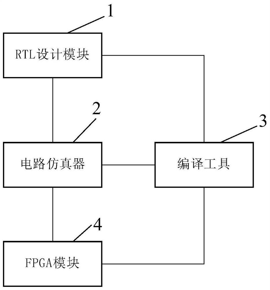
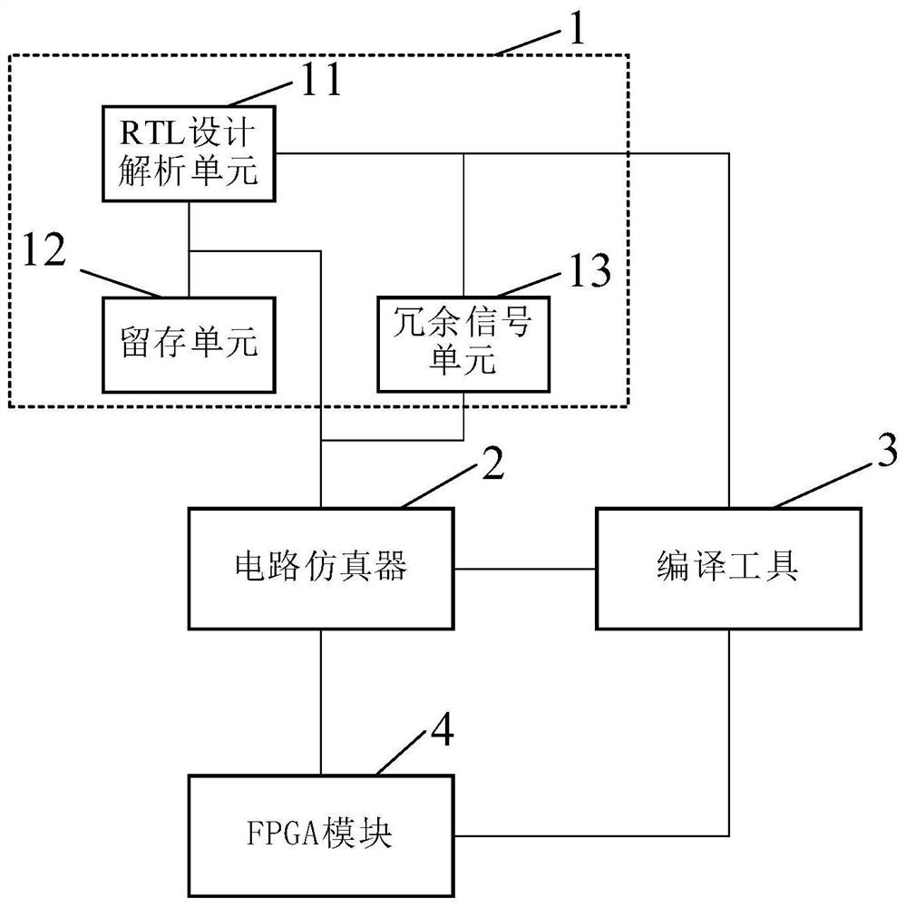
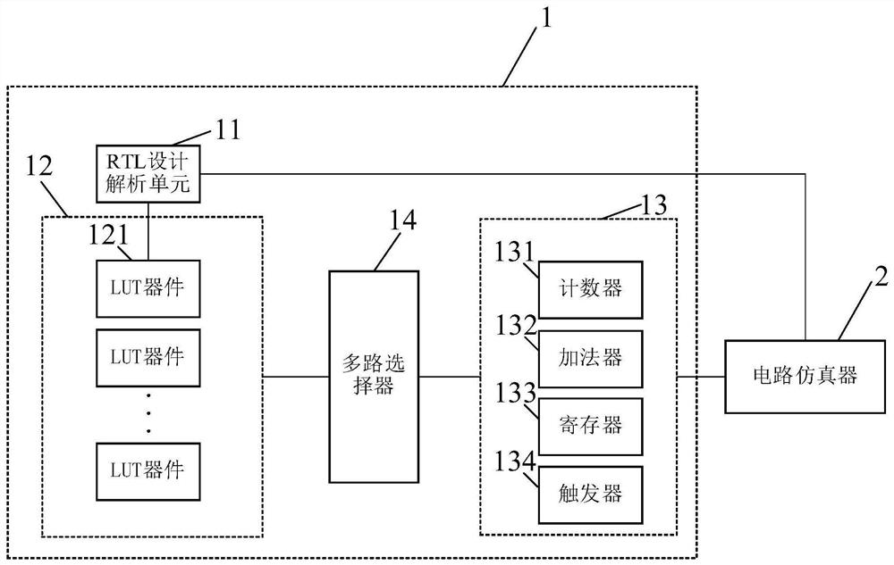
The embodiment of the invention provides a FPGA-based prototype verification device and method, and relates to the technical field of prototype verification. The prototype verification device based on the FPGA comprises an RTL design module, a circuit simulator, a compiling tool and an FPGA module which are connected with one another, and the RTL design module is used for obtaining a plurality of key signals in an RTL design file, storing hierarchical paths of the key signals and generating a constraint list based on the hierarchical paths of the key signals at all levels; the RTL design module is further used for obtaining a plurality of redundant signals in the RTL design file according to the key signals at all levels; the circuit simulator is used for generating a configuration file of the compiling tool based on each level of key signals and the plurality of redundant signals; the compiling tool is further used for obtaining a test file for prototype verification according to the RTL design file, the constraint list and the configuration file; and the FPGA module is used for performing prototype verification by using the test file. According to the invention, the error checking period of prototype verification is shortened, and the debugging period of prototype verification is accelerated.

Description

technical field [0001] The invention relates to the technical field of prototype verification, in particular to an FPGA-based prototype verification device and method. Background technique [0002] In the process of building and debugging FPGA (Field-Programmable Gate Array, programmable logic array) prototype verification platform, error checking technology is a very important means of quality verification. At present, there are two kinds of error-checking technologies commonly used in the FPGA platform. One is to insert error-checking logic into the Register Transfer Level (RTL) design, which is based on the error-checking logic analyzer (ILA core) and compiler tool (Vivado) error-checking technology; the other is to insert error-checking logic in the gate-level netlist, which is based on the error-checking technology of an intelligent integrated circuit emulator (IICE core) and a compilation tool (Synplify or Protocompiler); thus being able to When the FPGA is debugging,...

Claims


Application Information

Patent Timeline
Patent Type & Authority Applications(China)
IPC IPC(8): G06F30/327G06F30/367G06F30/34
CPCG06F30/327G06F30/367G06F30/34Y02D10/00
Inventor 不公告发明人
Owner 中天恒星(上海)科技有限公司
Learn More