Semiconductor device and heat sink bonding method

A semiconductor and heat sink technology, which is applied in semiconductor devices, semiconductor/solid-state device manufacturing, semiconductor/solid-state device components, etc., can solve problems that affect the polarization performance of semiconductor devices, local distortion of semiconductor devices, and cracks in semiconductor devices. The effect of uneven stress, reducing stress concentration, and reducing stress

Active Publication Date: 2021-09-03
度亘激光技术(苏州)有限公司
View PDF6 Cites 0 Cited by
  • Summary
  • Abstract
  • Description
  • Claims
  • Application Information

AI Technical Summary

Problems solved by technology

[0003] However, the general semiconductor device is thin and slender. When it is bonded to the heat sink, some stress generated by the welding of the semiconductor device and the heat sink can easily cause local distortion of the semiconductor device. After the semiconductor device is twisted, it will affect the polarization performance of the semiconductor device. , in severe cases, it may also lead to cracks or breakage of semiconductor devices

Method used


Image

  • Semiconductor device and heat sink bonding method
  • Semiconductor device and heat sink bonding method
  • Semiconductor device and heat sink bonding method

Examples


Embodiment Construction

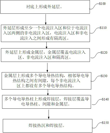
[0033] The technical solutions in the embodiments of the present application will be clearly and completely described below in conjunction with the drawings in the embodiments of the present application.

[0034]In the description of this application, it should be noted that the orientation or positional relationship indicated by the terms "inner", "outer", etc. is based on the orientation or positional relationship shown in the drawings, or the usual placement of the application product when it is used. Orientation or positional relationship is only for the convenience of describing the present application and simplifying the description, and does not indicate or imply that the referred device or element must have a specific orientation, be constructed and operated in a specific orientation, and thus should not be construed as limiting the present application. In addition, the terms "first", "second", etc. are only used for distinguishing descriptions, and should not be constr...


PUM


Abstract

The invention provides a semiconductor device and a heat sink bonding method, and relates to the technical field of semiconductors, and the method comprises the steps: forming an epitaxial layer on a substrate, wherein the epitaxial layer forms at least one current injection region and non-current injection regions located on the two sides of the current injection region, and an isolation region is formed between the current injection region and the non-current injection region; forming a metal layer on the epitaxial layer, wherein the metal layer covers the current injection region, the non-current injection region and the isolation region; forming a plurality of electric conduction and heat conduction structures on the metal layer, forming gaps between adjacent electric conduction and heat conduction structures, and arranging a plurality of electric conduction and heat conduction structures on each non-current injection region; forming a welding layer on the plurality of conductive and heat-conducting structures, wherein the welding layer covers the conductive and heat-conducting structures, the gap and the metal layer; and welding the heat sink and the welding layer. The electric conduction and heat conduction structure ensures that the current injection region is not stressed, and welding stress concentration is reduced when the heat sink is welded; the formation of the metal layer and the conductive and heat-conducting structure reduces the welding stress of the heat sink and the semiconductor device, and reduces or avoids local distortion of the semiconductor device caused by welding.

Description

technical field [0001] The present application relates to the field of semiconductor technology, in particular to a method for bonding a semiconductor device and a heat sink. Background technique [0002] Semiconductor devices will generate heat when they work. In order to make the semiconductor devices dissipate heat in time to ensure the performance of semiconductor devices, heat sinks are often used to dissipate heat from semiconductor devices, and the semiconductor devices and heat sinks are bonded by welding to achieve the purpose of semiconductor device heat dissipation. . [0003] However, the general semiconductor device is thin and slender. When it is bonded to the heat sink, some stress generated by the welding of the semiconductor device and the heat sink can easily cause local distortion of the semiconductor device. After the semiconductor device is twisted, it will affect the polarization performance of the semiconductor device. In severe cases, it may also cau...

Claims


Application Information

Patent Timeline
IPC IPC(8): H01L21/50H01L23/373B23K1/00
CPCH01L21/50H01L23/373B23K1/0008B23K2101/40
Inventor 杨国文王希敏
Owner 度亘激光技术(苏州)有限公司
Why Eureka
Try Eureka