Automatic hot pressing equipment

A hot-pressing equipment and automatic technology, applied in the field of hot-pressing, can solve the problems of wasting heat energy and time, poor precision of hot-pressing, excessive heat, etc., and achieve the effect of saving heat energy, saving heating time, and improving hot-pressing efficiency

Active Publication Date: 2021-09-07
珠海捷派自动化科技有限公司
View PDF11 Cites 0 Cited by
  • Summary
  • Abstract
  • Description
  • Claims
  • Application Information

AI Technical Summary

Problems solved by technology

This method is labor-intensive for workers, and the accuracy of hot pressing is not guaranteed, the assembly efficiency is low, and the assembly quality is unstable.
[0003] In the prior art, semi-automatic hot-pressing equipment began to appear. The worker places the plastic plate on a positioning plate, and then puts the nuts into the semi-automatic hot-pressing equipment, such as an automatic hot-pressing seven-point hot-pressing device disclosed in CN202020117427.0. Nut equipment presses multiple nuts onto the plate at the same time through the cylinder. However, these semi-automatic equipment only use machinery to replace labor in the hot pressing process. The nuts still need to be placed in the corresponding positions manually, and the efficiency improvement is not significant. Moreover, in the prior art, the heating of the nut is generally done by coil eddy current heating the nut or by contacting a resistance heating wire with the nut to conduct heat transfer. The whole nut is heated and consumes more heat. Cooling down for a certain period of time is a waste of heat energy and time. In fact, it is only necessary to heat the nut near the contact surface during pressing. However, because the heat diffusion speed in the nut is greater than the speed of heat conduction from the outside contact, and the existing The heating method most used in technology is contact heat transfer, so the heat is inevitably dispersed to the nut as a whole

Method used


Image

  • Automatic hot pressing equipment
  • Automatic hot pressing equipment
  • Automatic hot pressing equipment

Examples


Embodiment Construction

[0029] Next, the technical solutions in the embodiments of the present invention will be apparent from the embodiment of the present invention, and it is clearly described, and it is understood that the described embodiments are merely embodiments of the present invention, not all of the embodiments. Based on the embodiments of the present invention, there are all other embodiments obtained without making creative labor without making creative labor premises.

[0030] See Figure 1-7 The present invention provides a technical solution:

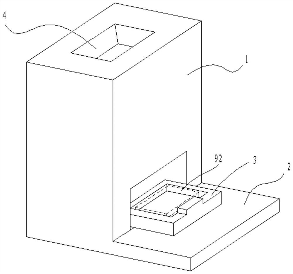
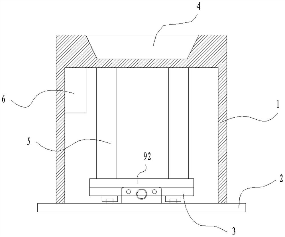
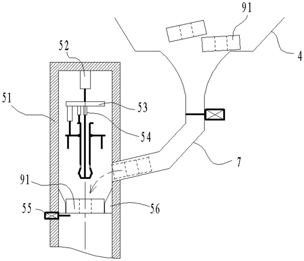
[0031]An automatic hot pressing device including housings 1, the bottom plate 2, the positioning plate 3, the silo 4, the airwand passage 5, the controller 6, and the introduction passage 7, and the housing 1 is disposed on the bottom plate 2, the housing 1 inside the bottom Set the positioning plate 3, the falling passage 5, and the controller 6, the positioning plate 3 is located at the bottom of the housing 1, and the silo 4 is disposed at the t...


PUM


Abstract

The invention discloses automatic hot pressing equipment which comprises a shell, a bottom plate, a positioning plate, a stock bin, discharging channels, a controller and guide-in channels. The shell is arranged on the bottom plate, the positioning plate, the discharging channels and the controller are arranged at the bottom in the shell, the positioning plate is located at the bottom in the shell, the stock bin is arranged at the top of the shell, the multiple discharging channels are vertically arranged, the upper portions of the discharging channels are connected with the stock bin through the guide-in channels, the controller is electrically connected with the discharging channels, and discharging switches are arranged on the guide-in channels. A plastic plate into which nuts are to be pressed is placed on the positioning plate, a plurality of nuts to be pressed into the plastic plate are placed in the stock bin, the nuts enter the upper portions of the discharging channels from the leading-in channels, the nuts are pressed down in the discharging channels, the nuts are heated in the downward movement process, after the nuts make contact with the plastic plate, downward pressure is continuously applied by parts in the discharging channels, the nuts are pressed into the plastic plate, and the multiple discharging channels synchronously press the nuts into the plastic plate.

Description

Technical field [0001] The present invention relates to a hot pressing technique, and in particular to an automatic pressing equipment. Background technique [0002] Some electronic devices often need to install a copper plate plastic nut for a threaded member removably connecting the small, plastic loaded manner nut plate into the hot zone is generally, either manually operated conventionally employed for this operation is completed, the worker nuts heated to a first temperature, and then use the position corresponding to the clamp nut is placed in the plastic plate, hot pressing operation. This way the workers labor-intensive, but not guarantee the accuracy of hot, low assembling efficiency, unstable quality of assembly. [0003] In the prior art, semi-automated began pressing equipment, worker plastic plate was placed into a positioning plate, and the nut pressing into the semi-automatic device, for example an automatic hot seven points disclosed CN202020117427.0 nut device, b...

Claims


Application Information

Patent Timeline
Patent Type & Authority Applications(China)
IPC IPC(8): B29C65/44B29C65/78
CPCB29C65/44B29C65/7841B29C65/7858B29C66/74281
Inventor 刘付承彬
Owner 珠海捷派自动化科技有限公司
Why Eureka
Try Eureka